Radio frequency identification system test board

A radio frequency identification system and test bench technology, applied in the direction of measuring electricity, measuring devices, measuring electrical variables, etc., can solve the problems of less, difficult and time-consuming radio frequency identification system testing, and achieve wide application range, low cost and wide application range wide effect

Inactive Publication Date: 2010-08-18
HUNAN UNIV
View PDF6 Cites 21 Cited by
  • Summary
  • Abstract
  • Description
  • Claims
  • Application Information

AI Technical Summary

Problems solved by technology

Although the radio frequency identification technology is relatively mature and there are many corresponding products, there are still few tests on the radio frequency identification system. In actual use, the installation position of the radio frequency identification system reader, the attachment position of the label, and the moving speed of the item must be tested. Repeatedly installing, testing, then removing, and reinstalling in another location for subsequent testing is time consuming and difficult

Method used


Image

  • Radio frequency identification system test board
  • Radio frequency identification system test board
  • Radio frequency identification system test board

Examples


Embodiment 1

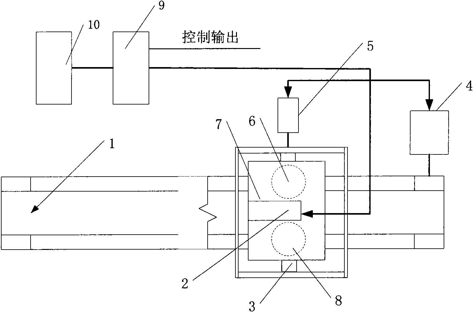
[0026] A radio frequency identification system test bench is characterized in that it includes a host computer, a PLC controller, a conveyor for transmitting radio frequency tags, an antenna rotating turntable and an antenna turntable workbench for adjusting the directions of transmitting antennas and receiving antennas; radio frequency tags are attached On the attached material, the attached material is placed on the conveying belt of the conveyor; the conveyor is driven by a frequency conversion motor; the antenna rotating turntable is set above the conveying belt of the conveyor, and the antenna rotating turntable is equipped with a turntable that drives the antenna rotating turntable table to rotate Horizontal axis; the brake motor is connected to the horizontal axis of the turntable through a two-stage reducer;

[0027] The antenna turntable table is equipped with two antenna turntables, namely the first antenna turntable and the second antenna turntable, both of which are...


PUM


Abstract

The invention discloses a radio frequency identification system test board. The test board comprises an upper computer, a PLC controller, a conveyer, an antenna revolving table and an antenna rotary table, wherein the conveyer is used for transmitting a radio frequency tag; the antenna revolving table is used for adjusting the directions of a transmitting antenna and a receiving antenna; the conveyor is driven by a variable frequency motor; the antenna revolving table is arranged above a conveyer belt of the conveyor; a brake motor is connected with a rotary table transverse shaft through a two-stage speed reducer and is used for adjusting the pitch angle of the antenna; a servo motor is in transmission connection with the antenna rotary table through a driving mechanism which is used for driving a first antenna turntable and a second turntable to rotate synchronously and reversely, and is used for adjusting the azimuth angles of the transmitting antenna and the receiving antenna; the transmitting antenna and the receiving antenna are connected with the upper computer through a measuring device; and control ends of the variable frequency motor, the brake motor and the servo motor are connected with the output end of the PLC controller. The test board can simulate a practical application scene to perform a comprehensive test on the radio frequency tag and has high automatic degree.

Description

technical field [0001] The invention belongs to the field of automatic detection devices of radio frequency tags, and in particular relates to a radio frequency identification system test platform. Background technique [0002] Radio frequency identification technology is widely used in industrial automation, logistics management, transportation management, anti-counterfeiting, security management and other fields. Although the radio frequency identification technology is relatively mature and there are many corresponding products, there are still few tests on the radio frequency identification system. In actual use, the installation position of the radio frequency identification system reader, the attachment position of the label, and the moving speed of the item must be tested. Repeatedly installing, testing, then removing, and reinstalling in another location for subsequent testing is time consuming and difficult. Therefore, there is a need for a radio frequency identifi...

Claims


Application Information

Patent Timeline
Patent Type & Authority Applications(China)
IPC IPC(8): G01R31/00G06K7/00
Inventor 何怡刚李兵侯周国佘开朱彦卿廖华兵佐磊
Owner HUNAN UNIV
Why Eureka
Try Eureka