Channel coding method for enhancing transmission quality of fountain code on wireless channel

A wireless channel and channel coding technology, applied in transmission systems, digital transmission systems, electrical components, etc., can solve problems such as errors, cannot be effectively prevented, decoding errors, etc., to achieve the effect of improving transmission quality

Inactive Publication Date: 2010-08-18
ZHEJIANG UNIV
View PDF0 Cites 14 Cited by
  • Summary
  • Abstract
  • Description
  • Claims
  • Application Information

AI Technical Summary

Problems solved by technology

[0004] However, only in a wired environment, the lack of fountain codes does not necessarily have the good performance on the erasure channel mentioned earlier, that is because the wireless channel is not an erasure channel but an interference channel, so the receiving end receives in the wireless channel The LT codes may contain errors
According to the encoding method of the LT encoder, once the wrong LT codes enter the LT decoder, a series of LT decoding errors (error propagation) will be caused, and the final source data packet cannot be completely recovered correctly.
Although an ordinary Forward Error Correction Encoder (FEC) can be cascaded behind the LT encoder at the sending end to channel encode the generated LT codes, and then perform FEC decoding on the interfered data packets received on the channel through the receiving end , in order to reduce the possibility of the LT decoder at the receiv...

Method used


Image

  • Channel coding method for enhancing transmission quality of fountain code on wireless channel
  • Channel coding method for enhancing transmission quality of fountain code on wireless channel
  • Channel coding method for enhancing transmission quality of fountain code on wireless channel

Examples


Embodiment Construction

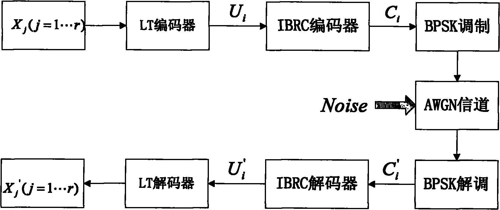
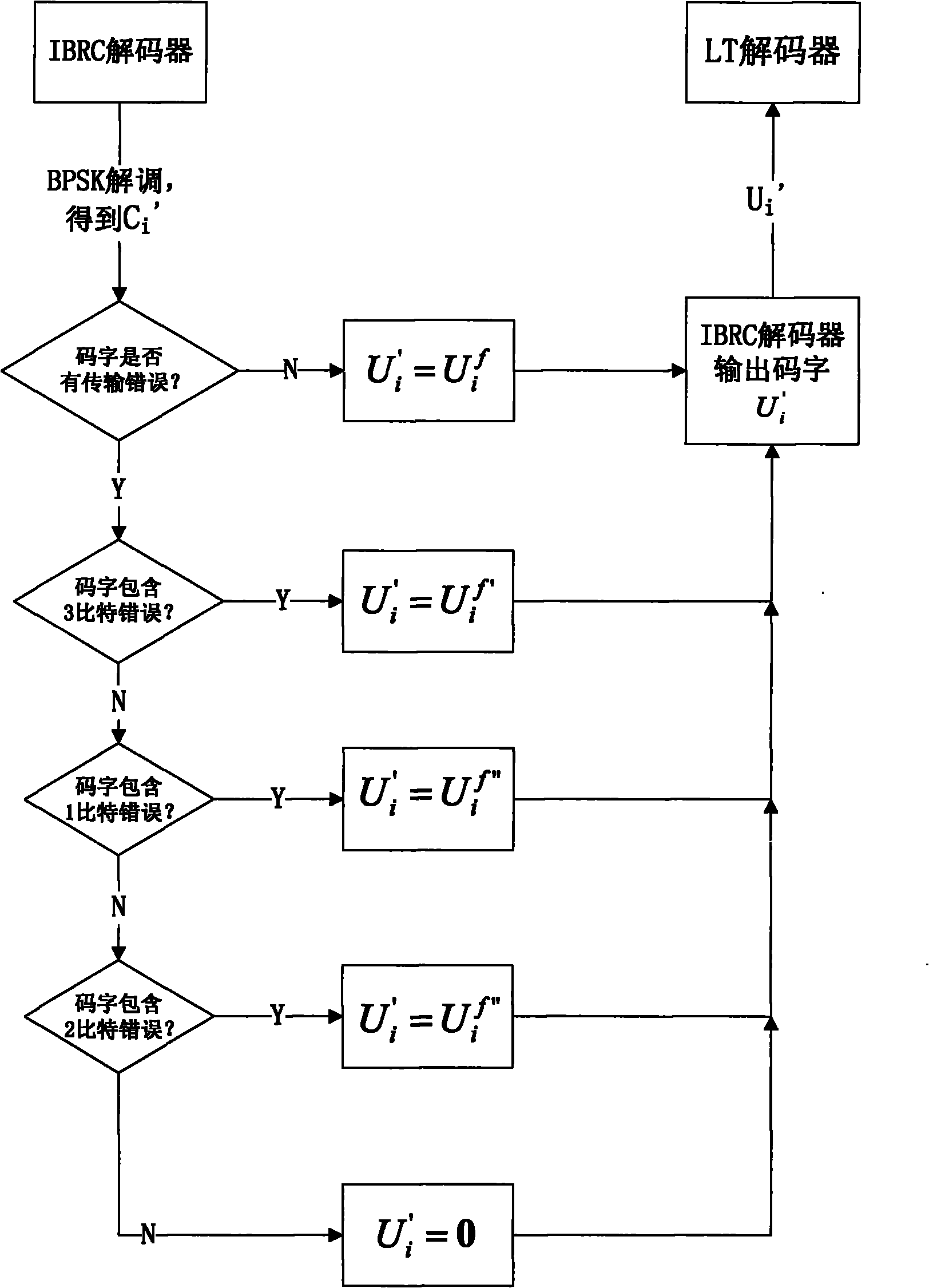
[0042] figure 1 It is a structural schematic diagram of the fountain code transceiver system including IBRC used in the present invention. The sending end includes an LT encoder and a subsequent concatenated IBRC encoder, and the receiving end includes an IBRC decoder and a subsequent concatenated LT decoder. The source data at the sender contains r codewords X j (j=1...r), these codewords first pass through the LT encoder to form an infinite number of LT codes, for each LT code (U i ), U i First pass through the IBRC coder for channel coding, and then form the corresponding IBRC code word C i Then perform BPSK modulation, and finally the IBRC channel encoder sends the BPSK-modulated IBRC code word to the receiving end through the AWGN channel, and the receiving end performs BPSK demodulation after receiving the code word, and obtains some Bit-erroneous encoded IBRC codeword C i ’, IBRC decoder for C i ’ to decode, and the obtained decoding result U i 'Send it to the LT...


PUM


Abstract

The invention discloses a channel coding method for enhancing the transmission quality of a fountain code on a wireless channel, which comprises the following steps of: when coding an IBRC channel, sequentially displacing input code words firstly by an IBRC coder circularly through taking each element in two displacement vectors as the amplitude of the circular displacement of each time sequentially, then carrying out modular two addition on all the obtained code words after displacing circularly to obtain two code words totally, afterwards cascading the two code words to obtain coding code words, modulating by using BPSK and transmitting; when decoding the IBRC channel, dividing the received code words into a front section and a back section after carrying out BPSK demodulation on the received code words by an IBRC decoder, then carrying out modular two addition, afterwards carrying out reverse circular displacement, determining whether IBRC code words are erroneous in the transmission process or not on the basis of the code words obtained after displacing circularly, and outputting the code words directly if the IBRC code words are not erroneous; otherwise, setting an erroneous bit number sequentially within a certain range, decoding under the setting, and outputting a decoding result if the decoding is successful; and if the set erroneous bit number is still not decoded successfully after the set erroneous bit number samples all integers in the range, outputting all-zero code words by the IBRC decoder.

Description

technical field [0001] The invention relates to a fountain code and a channel coding method of a wireless channel, belonging to the field of wireless data transmission. Background technique [0002] After LT codes and Raptor codes were proposed and studied as two implementation forms of fountain codes, fountain codes proved to be a data encoding method with excellent transmission performance and low complexity implementation process, so fountain codes were also It is regarded as an ideal means of transmission for realizing large-scale data broadcasting, and has been listed as a specific relevant standard of 3GPP and DVB-H. The key to this technology is to generate an infinite number of encoded codewords called LT codes from K source data packets through the core LT encoder, and the LT decoder at the receiving end only needs to correctly receive any code words slightly larger than K The N LT codes of N LT codes can recover about K source data packets. [0003] The tradition...

Claims


Application Information

Patent Timeline
IPC IPC(8): H04L1/00
Inventor 吕思达赵志峰崔云陈琴琴王晓危彦杨杰夏雨王龙威张广超王峰周斌
Owner ZHEJIANG UNIV
Why Eureka
Try Eureka