Screen
A screen, retro-reflection technology, applied in the field of screens, can solve problems such as difficulty in spacing
Inactive Publication Date: 2010-08-18
SHARP KK
View PDF5 Cites 22 Cited by
- Summary
- Abstract
- Description
- Claims
- Application Information
AI Technical Summary
Problems solved by technology
However, in practice, it is difficult to manufacture a cube-corner reflector array with a small pitch (for example, below 100 μm) into an ideal shape
Method used
View moreImage
Smart ImageViewing Examples
Examples
Embodiment approach 1
Embodiment approach 2
Login to View More PUM
 Abstract
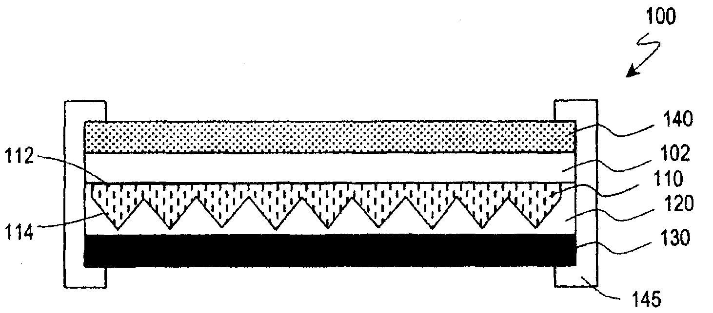
A screen (100) is provided with a retroreflective layer (110) comprised of a front surface (112) and a rear surface (114) on which a corner cube array is arranged; a low refractive index layer (120) made of a material that has a lower refractive index than that of the retroreflective layer (110); and a light absorptive layer (130) that absorbs at least a part of light that is incident on the retroreflective layer (110) from the front surface (112) of the retroreflective layer (110) and is projected from the rear surface (114) to the low refractive index layer (120). In a certain embodiment, at least a part of the light absorptive layer (130) is provided opposite to the corner cube array of the retroreflective layer (110) through the low refractive index layer (120).
Description
technical field The present invention relates to screens for use with projectors. Background technique A projection system uses a small projector (projector) to display a large-screen image on a screen. Therefore, projection systems are widely used in presentations such as movie theaters and home theater movie audiovisuals and conferences. The projector emits high-intensity projected light during bright display and low-intensity projected light during dark display. In a front projection type projection system that can be used in a narrow space more easily than a rear projection type, a screen that diffuses and reflects incident light is generally used. Since the screen diffusely reflects the projected light from the projector, more observers can observe the image. However, since the screen performing diffuse reflection also diffusely reflects ambient light other than projected light, when the surroundings of the screen are bright, the screen appears bright regardless of ...
Claims
Login to View More Application Information
Patent Timeline
 Patent Type & Authority Applications(China)
IPC IPC(8): G03B21/60G02B5/02G02B5/124G03B21/10
CPCG03B21/60G02B5/128G02B2027/0118G02B27/0172G02B5/30G02B5/124G02B5/045
Inventor 箕浦洁佐藤英次浅冈康
Owner SHARP KK
Features
- R&D
- Intellectual Property
- Life Sciences
- Materials
- Tech Scout
- Unparalleled Data Quality
- Higher Quality Content
- 60% Fewer Hallucinations
Learn More Browse by: Latest US Patents, China's latest patents, Technical Efficacy Thesaurus, Application Domain, Technology Topic, Popular Technical Reports.
© 2025 PatSnap. All rights reserved.Legal|Privacy policy|Modern Slavery Act Transparency Statement|Sitemap|About US| Contact US: help@patsnap.com


