

Self-sucking energy-saving high-efficiency water pump
A high-efficiency, water pump technology, applied in the direction of pumps, rotary piston pumps, rotary piston machines, etc., can solve the problems of failing to achieve the use effect and work efficiency, difficult to meet market needs, high noise, etc., and achieve a simple product structure. Design, enhance pumping efficiency, reduce noise
Inactive Publication Date: 2010-08-25
黄武源
View PDF7 Cites 8 Cited by
- Summary
- Abstract
- Description
- Claims
- Application Information
AI Technical Summary
Problems solved by technology
However, although the existing water pump structure can provide its basic water pumping function, in actual use, it is found that there are still many deficiencies in its own structure and performance, and it cannot achieve the best use effect and work efficiency.
Its disadvantages are: small flow, low efficiency, high noise, high cost, and it is difficult to meet the increasingly competitive market needs
Method used
View moreImage
Smart ImageViewing Examples

Examples
Embodiment Construction
Login to View More PUM
 Abstract
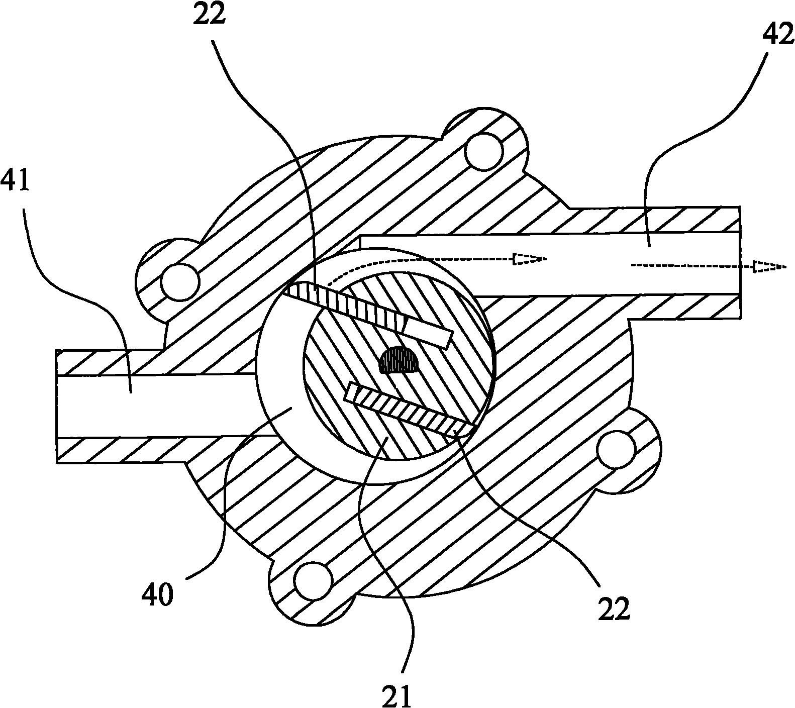
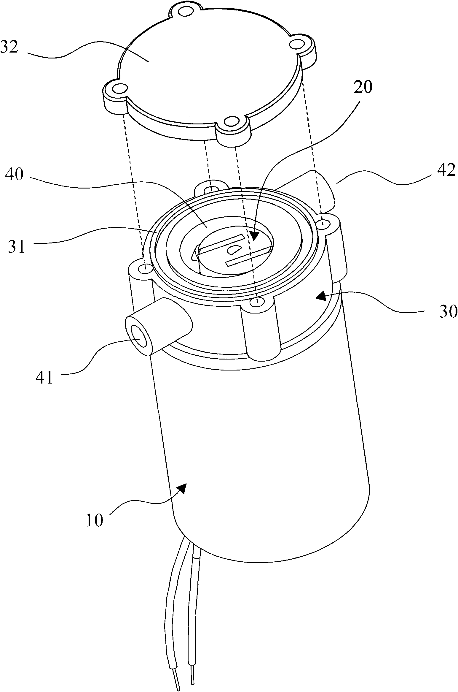
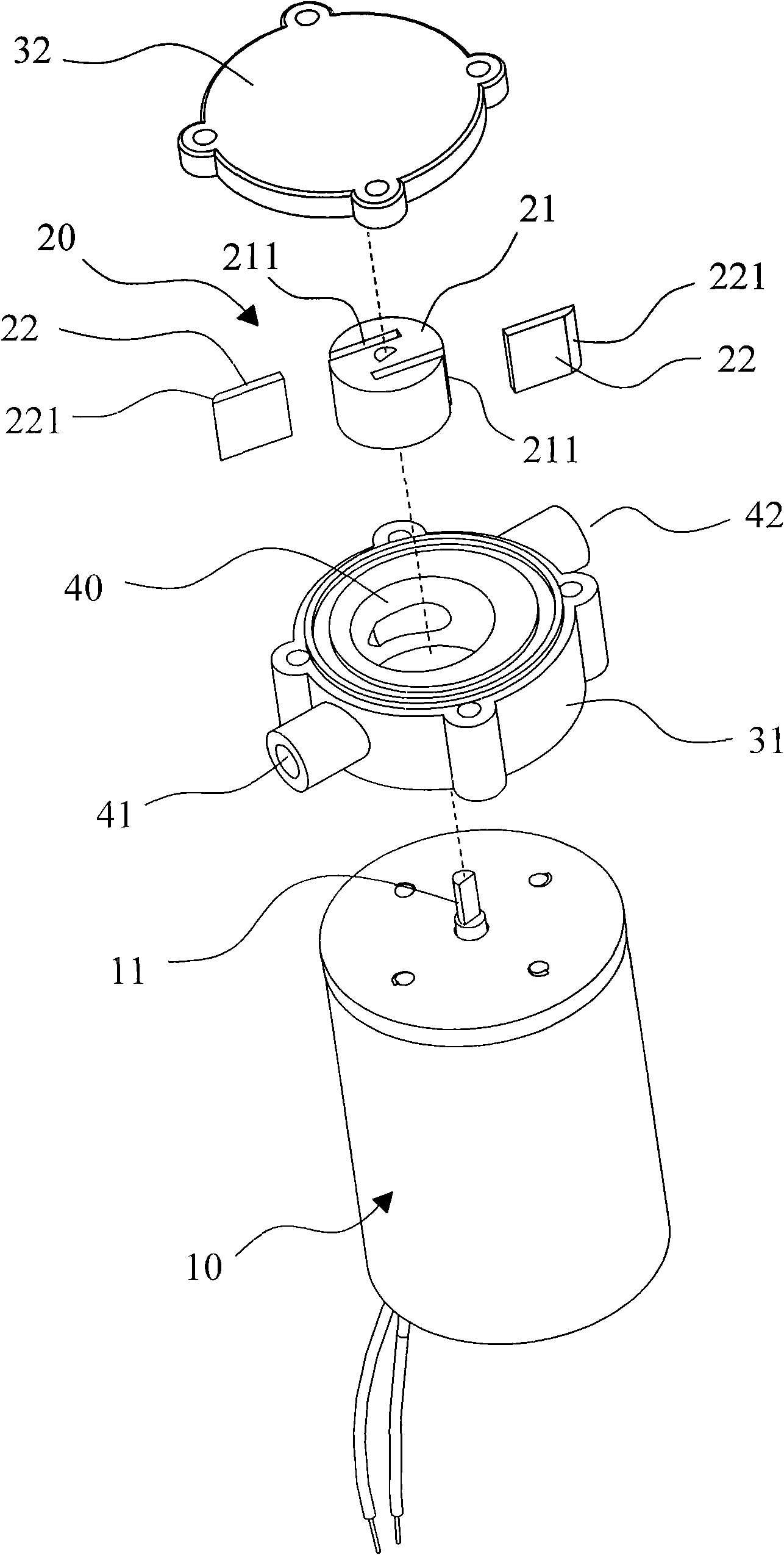
The invention discloses a self-sucking energy-saving high-efficiency water pump, which comprises an impeller and a pump shell, wherein the impeller is positioned in a liquid chamber of the pump shell and connected to a driving device which drives the impeller to rotate to form a water current for water pumping; the liquid chamber has a water inlet and a water outlet; the impeller comprises a hub and blades; the liquid chamber is eccentrically arranged relative to the hub; one side of the hub is close to the inner wall surface of the liquid chamber, so the volume between the other side of the hub and the inner wall surface of the liquid chamber is big, the water inlet of the liquid chamber is communicated with the large volume area and the water outlet of the liquid chamber is communicated with the position, where the volume reduces gradually, of the liquid chamber; and the blades can be moveably arranged in the hub relative to the hub. When the hub rotates, the blades extend outwards under the action of the centrifugal force, the tail ends of the blades are matched with the inner wall surface of the liquid chamber and extend radially along with the volume change of the liquid chamber to drive the water current, and thus, the water current flows towards the water outlet only. The self-sucking energy-saving high-efficiency water pump avoids the diffusion and reflux of the water current, improves the pumping efficiency and the flow and has the advantages of saving the energy and protecting the environment.
Description
Self-priming energy-saving and high-efficiency water pump technical field The invention relates to the technology in the field of water pumps, in particular to a water pump that utilizes the cooperation of an eccentric liquid chamber and movable blades to obtain high-efficiency water pumping. Background technique At present, water pumps have been widely used in water circulation such as electronic refrigerators, ice bladders, hot water bottles, aquarium fish tanks, fountains, solar energy and handicrafts. The structure of the water pump is basically composed of a pump casing and an impeller, and is used with a motor. The pump casing is provided with a water inlet and a water outlet. The impeller is set in the liquid chamber of the pump body, and the outlet is connected to the side of the liquid chamber. The direction of the outlet is consistent with the tangential direction of impeller rotation. Its working principle is to use the motor to drive the impeller to rotate at ...
Claims
Login to View More Application Information
Patent Timeline
 IPC IPC(8): F04C2/344
Inventor黄武源
Owner黄武源