Suspension support speed reducing transmission device

A technology of reduction transmission and reducer, which is applied in the field of reduction transmission and suspension support reduction transmission, which can solve the problems of repeated impact, failure of transmission keys, inability to adjust the mutual position of the motor and the primary reducer, etc., to achieve convenient disassembly and assembly, and convenient The effect of maintenance

Inactive Publication Date: 2010-08-25
SHANGHAI MEISHAN IRON & STEEL CO LTD
View PDF0 Cites 2 Cited by
  • Summary
  • Abstract
  • Description
  • Claims
  • Application Information

AI Technical Summary

Problems solved by technology

At present, the primary reducer of this type of mechanism adopts a fixed flange connection support method, so the mutual position cannot be adjusted according to the assembly requirements of the motor and the primary reducer, and the disassembly and assembly of the primary reducer requires a lot of work
In addition, the connection between the primary reducer and the secondary reducer usually adopts the method of gap fit between the e

Method used


Image

  • Suspension support speed reducing transmission device
  • Suspension support speed reducing transmission device
  • Suspension support speed reducing transmission device

Examples


Embodiment 1

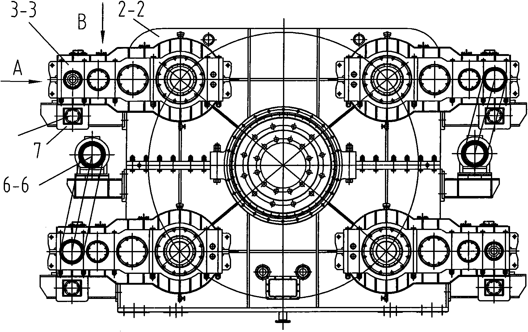
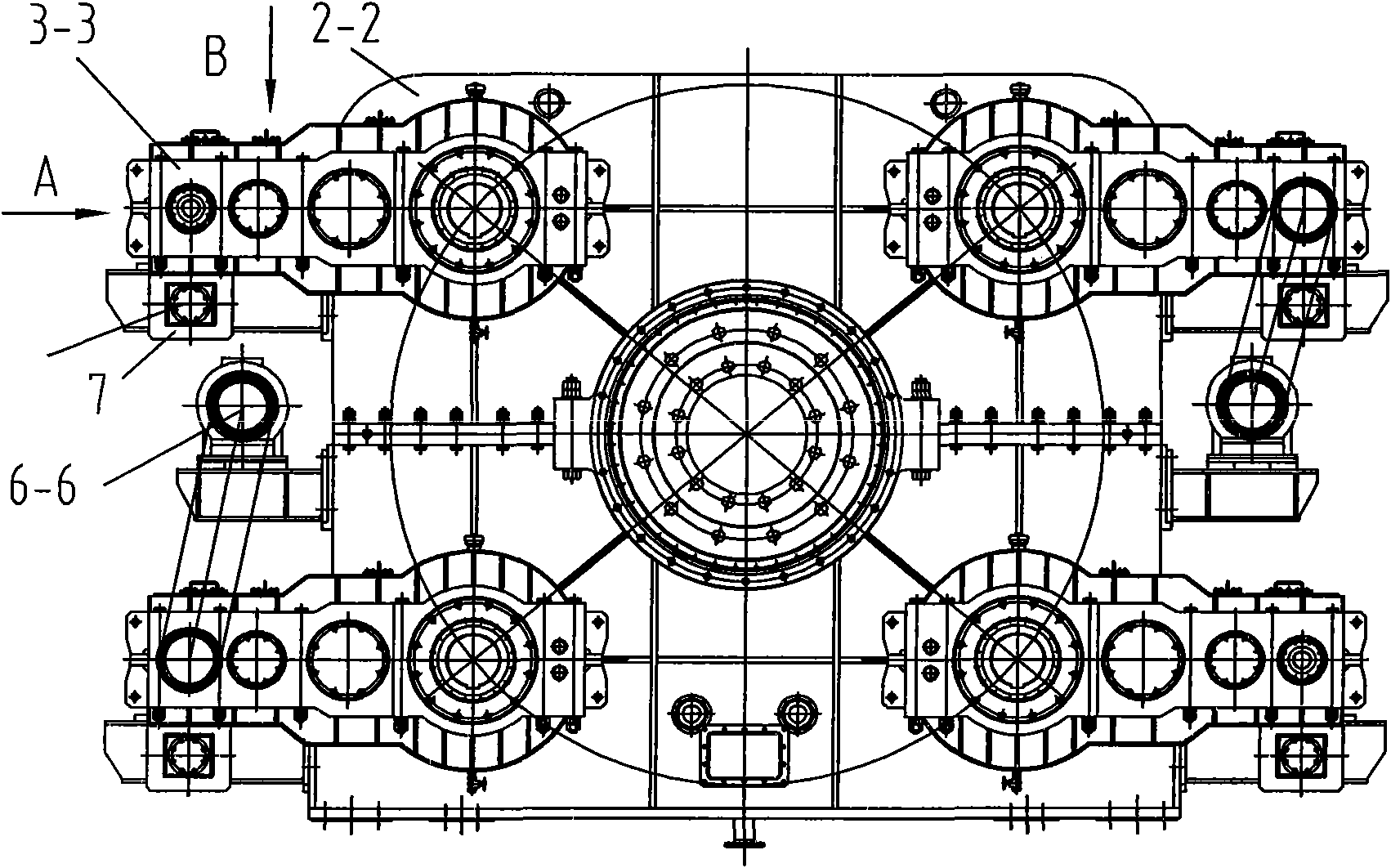
[0016] This embodiment is a suspension support deceleration transmission device adopted by a converter tilting mechanism in the iron and steel smelting industry. As shown in Figure 1, the four groups of motors drive the secondary decelerator 2-2 through their respective primary decelerators 3-3, two of which A primary reducer also drives the air motor 6-6 through the belt drive simultaneously.

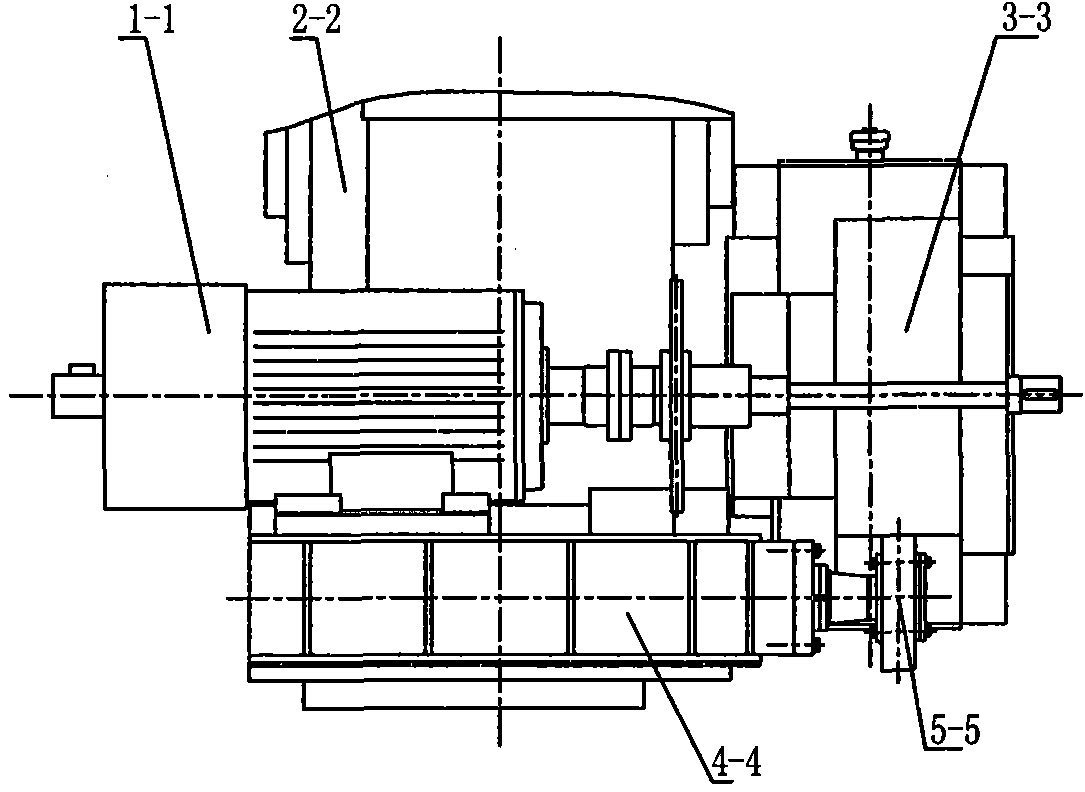
[0017] As shown in Fig. 2 and Fig. 3, the motor 1-1 is installed on the motor support 4-4, and the motor support is fixedly connected with the casing of the secondary reducer 2-2. The output shaft of the motor 1-1 is coupled with the input end shaft of the primary reducer 3-3, and the gear sleeve 18 as the output end of the primary reducer is directly coupled with the gear shaft 17 as the input end of the secondary reducer. The specific structure is a gear shaft 17 is connected with the gear sleeve 18 through a key, and the gear shaft 17 is fixed on the gear sleeve 18 with the bolt 16 ...


PUM


Abstract

The invention relates to a suspension support speed reducing transmission device, which belongs to the technical field of a mechanical transmission device. The device comprises a motor, a primary speed reducer and a secondary speed reducer, wherein the motor is arranged on a motor support seat, the input end of the primary speed reducer is coupled with an output shaft of the motor, the input end of the secondary speed reducer is coupled with the output end of the primary speed reducer, the motor support seat is fixedly connected with a case of the secondary speed reducer, the motor support seat is sheathed with a support shaft through an eccentric shaft, the support shaft is parallel to the output shaft of the motor, a support seat block extends from one side of the case of the primary speed reducer, a slide block is arranged in the support seat block, a support hole is formed in the slide block, the slide block and the support seat block form a moving pair vertical to the direction of the output shaft of the motor, and the outer end of the support shaft is arranged in the support hole. The invention can conveniently regulate the assembly position of the motor and the primary speed reducer according to the requirement so that the motor and the primary speed reducer can be in an ideal transmission state. In addition, the structure brings great convenience for the dismounting and the installation of the primary speed reducer, and the repair and the maintenance are convenient.

Description

technical field [0001] The invention relates to a reduction transmission device, in particular to a suspension support reduction transmission device, which belongs to the technical field of mechanical transmission devices. Background technique [0002] As far as the applicant knows, the converter tilting mechanism needs to reduce the power output by the motor through the primary and secondary reducers. At present, the primary reducer of this type of mechanism adopts a fixed flange connection support method, so the mutual position cannot be adjusted according to the assembly requirements of the motor and the primary reducer, and the disassembly and assembly of the primary reducer requires a lot of work. In addition, the connection between the primary reducer and the secondary reducer usually adopts the method of gap fit between the extension shaft and the bushing, or the method of conical fit. The formation of repeated impacts causes the failure of the transmission key, and ...

Claims


Application Information

Patent Timeline
IPC IPC(8): F16H49/00F16C23/04F16C35/00F16C11/06F16B21/00F16B3/00
Inventor 张国日黄超陈德亮朱立江施卫忠尹晓春王贤慧
Owner SHANGHAI MEISHAN IRON & STEEL CO LTD
Why Eureka
Try Eureka