Roll angle detection method of directional firework shell and detection device thereof
A detection method and technology of fireworks bombs, which are applied in the field of roll angle detection method and detection device of directional fireworks bombs, can solve the problems of complex system, inapplicability of fireworks roll attitude detection, high cost of gyroscope, etc., and achieve small volume, The effect of low cost and simple circuit
Inactive Publication Date: 2010-08-25
NANJING UNIV OF SCI & TECH
View PDF0 Cites 6 Cited by
- Summary
- Abstract
- Description
- Claims
- Application Information
AI Technical Summary
Problems solved by technology
Method used
View moreImage
Smart ImageViewing Examples
Examples
Embodiment
Login to View More PUM
 Abstract
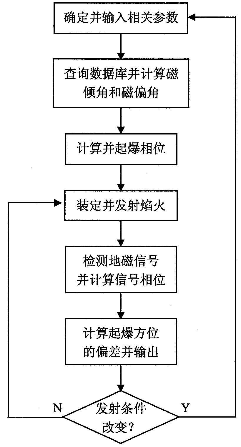
The invention discloses a roll angle detection method of a directional firework shell and a detection device thereof. The method comprises the steps of: firstly, determining and inputting related information of emitting the firework shell during detection; computing a local magnetic inclination and a local magnetic declination; computing a relatively top reference angle and an initiation phase; fixing the initiation phase to the firework shell, loading the firework shell and emitting; beginning to work by a shell-borne part after emitting the firework shell; detecting a geomagnetic signal by a magnetic detection circuit; computing the phase of the geomagnetic signal; finally computing the deviation of the initiation azimuth; and continuously outputting deviation signals to an attitude control device. When the deviation of the azimuth is 0, the initiation azimuth is needed. The detection device comprises a ground part and the shell-borne part. The detection method can be used for directly detecting the deviation of the initiation azimuth without integral or accumulated errors. The detection device has small volume, simple circuit, low cost and strong impact resistant performance.
Description
Roll Angle Detection Method and Detection Device of Directional Firework Bomb technical field The invention relates to a detection technology for firework bombs, in particular to a roll angle detection method and a detection device for directional fireworks bombs. Background technique With the development of pyrotechnics technology, various new types of pyrotechnic bombs continue to emerge, among which directional pyrotechnic bombs need to act under a given rolling attitude in order to give the required special effects. Although the attitude detection and control of traditional missiles is very mature, the cost of the gyroscope used for attitude detection is very high and the system is complex, which is not suitable for the roll attitude detection of fireworks bombs. Contents of the invention The purpose of the present invention is to provide a roll angle detection method and detection device for directional fireworks bombs, so that the fireworks bombs can be detonated ...
Claims
Login to View More Application Information
Patent Timeline
 IPC IPC(8): F42B35/02G01R33/09
CPCF42B4/06F42B15/01
Inventor 张合程翔丁立波张祥金李豪杰马少杰王志明
Owner NANJING UNIV OF SCI & TECH
Features
- R&D
- Intellectual Property
- Life Sciences
- Materials
- Tech Scout
- Unparalleled Data Quality
- Higher Quality Content
- 60% Fewer Hallucinations
Learn More Browse by: Latest US Patents, China's latest patents, Technical Efficacy Thesaurus, Application Domain, Technology Topic, Popular Technical Reports.
© 2025 PatSnap. All rights reserved.Legal|Privacy policy|Modern Slavery Act Transparency Statement|Sitemap|About US| Contact US: help@patsnap.com


