

Blood viscosity fast detection device and method thereof
A blood viscosity and detection device technology, applied in the direction of DC flow characteristic measurement, etc., can solve the problems of complex structure and inconvenient operation, and achieve the effects of accurate viscosity results, saving detection steps, and less demand for dosage.
Inactive Publication Date: 2010-08-25
蔡泳
View PDF8 Cites 10 Cited by
- Summary
- Abstract
- Description
- Claims
- Application Information
AI Technical Summary
Problems solved by technology
The measuring instrument for real-time detection of human blood viscosity has the characteristics of being able to eliminate operation and reading errors, high detection accuracy and high degree of automation; however, this measuring instrument also needs to be equipped with a temperature control unit, etc., so the structure is complicated and the operation is not easy enough
Method used
View moreImage
Smart ImageViewing Examples

Examples
Embodiment 1
Embodiment 2
Embodiment 3
Login to View More PUM
| Property | Measurement | Unit |
|---|---|---|
| diameter | aaaaa | aaaaa |
| length | aaaaa | aaaaa |
Abstract
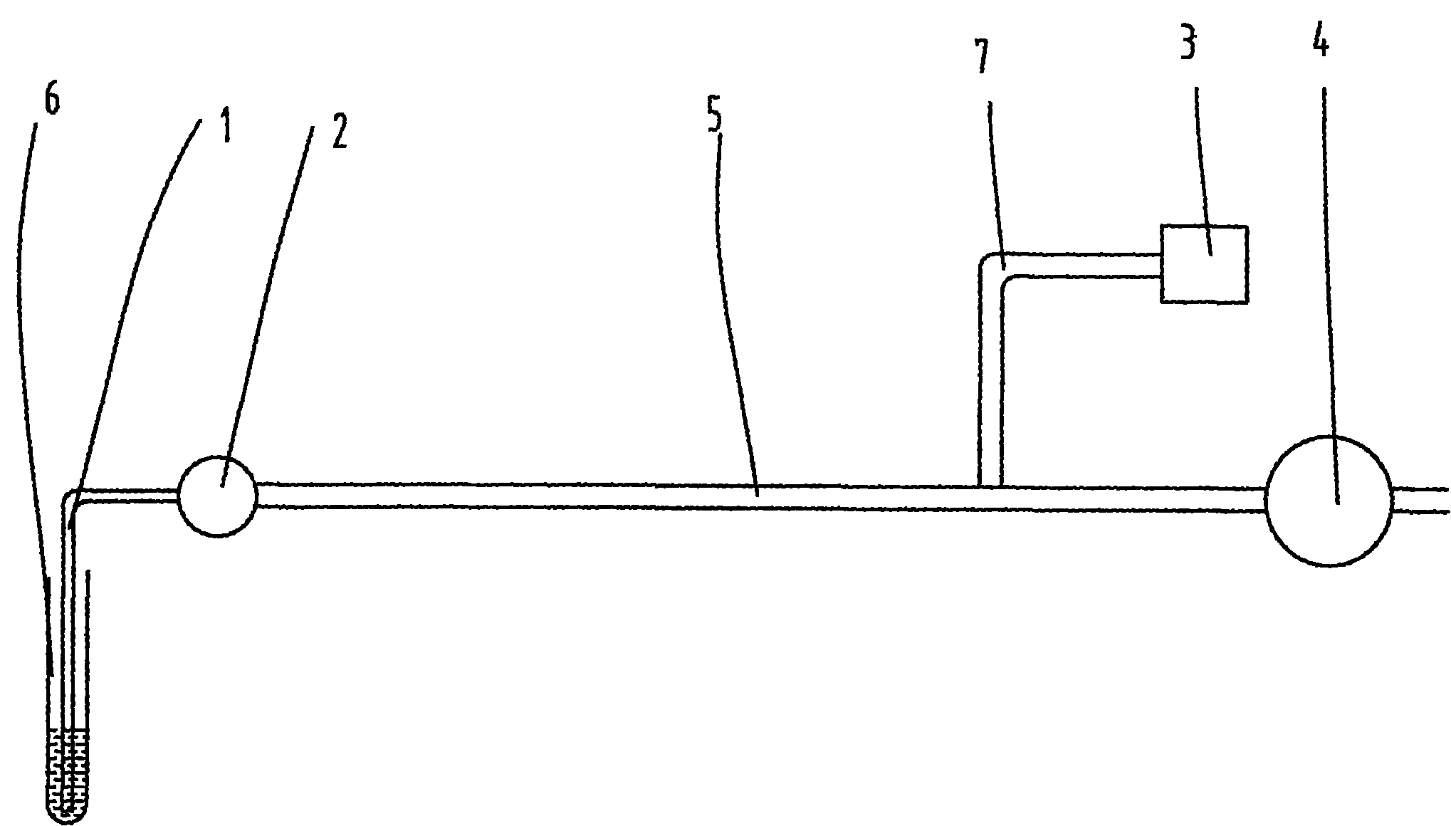
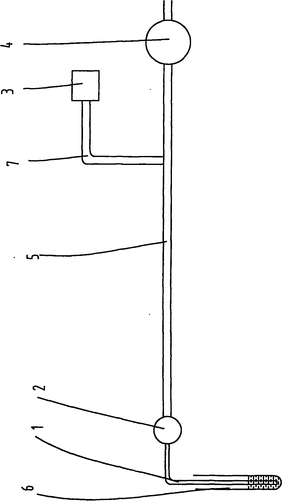
The invention discloses a blood viscosity fast detection device and a method thereof. The upper end of a sample feeding needle is connected with one end of an electromagnetic valve, the other end of the electromagnetic valve is connected with a peristaltic pump through a detection pipe, a baroceptor is arranged on the detection pipe between the electromagnetic valve and the peristaltic pump, and the pipe diameter of the detection pipe is greater than the pipe diameter of the sample feeding needle. The method adopts a negative pressure method for detecting the viscosity of blood samples, and collects the pressure change data in the detection pipe according to a principle that the flowing speed of fluids with different viscosities is in inverse proportion to the viscosities, and the viscosities of the fluids can be measured through the calculation via a pressure-viscosity mathematical model. The invention has the characteristics of high measurement precision, ingenious design, simple structure, easy implementation, good reliability and the like.
Description
Device and method for rapid detection of blood viscosity technical field The invention relates to a medical detection device and a method thereof, in particular to a rapid detection device and a method thereof for blood viscosity detection. Background technique In the medical field, measuring the viscosity of blood and other physiological fluids is a newly developed diagnostic method, especially for the diagnosis of cardiovascular diseases, cancer, tumors and other difficult diseases. However, the existing medical instruments for detecting blood viscosity are complicated to operate and require relatively large blood sampling procedures. The existing blood viscosity measurement methods mainly include capillary method, rotation method, falling body method, vibration method, plate method and so on. For example, the traditional capillary gravity method roughly compares and calculates the viscosity by comparing the flow time of the fluid in the vertical capillary. The measure...
Claims
Login to View More Application Information
Patent Timeline
 Patent Type & AuthorityApplications(China)
IPC IPC(8): G01N11/08
Inventor蔡泳
Owner蔡泳