

Method and equipment for automatic calibration of oil conductivity meter
An oil conductivity meter and the technology of oil conductivity, which are applied in the direction of material resistance, can solve the problems of continuous automatic multi-point verification of the oil conductivity meter, limited measurement range, and large resistance value intervals, so as to save manual workload, The effect of reducing human interference and large measurement range
Active Publication Date: 2010-08-25
NO 53 RES INST OF CHINA NORTH IND GRP
View PDF4 Cites 2 Cited by
- Summary
- Abstract
- Description
- Claims
- Application Information
AI Technical Summary
Problems solved by technology
The output point of this method is fixed, the resistance value interval is large, and the measurement range is limited. It is impossible to perform continuous automatic multi-point verification on the verified oil conductivity meter. The error is large, the work is cumbersome, and it is easy to make mistakes.
Method used
View moreImage
Smart ImageViewing Examples


Examples
Embodiment 1
Embodiment 2
Login to View More PUM
 Abstract
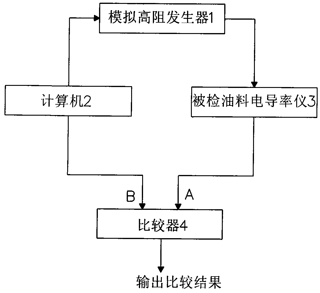
The invention provides a method for automatic calibration of an oil conductivity meter. The method comprises the following steps of: setting a simulated high-resistance generator to send a high-resistance signal to the oil conductivity meter to be calibrated; outputting a calibration signal A of the oil conductivity meter to be calibrated to a comparator, simultaneously making a signal processingdevice output a standard signal B to the comparator, and comparing the calibration signal A and the standard signal B; and outputting the comparison result. The method and the equipment for the automatic calibration of the oil conductivity meter have the advantages of realizing the automatic calibration, saving huge manual workload, making the calibration result transitioned from discrete quantity to continuous quantity, making the measurement more accurate and the measurement range more wide, improving calibration efficiency, and improving the reliability and stability of the calibration result.
Description
An automatic verification method and equipment for an oil conductivity meter technical field The invention belongs to the field of automatic measurement, and specifically relates to a method and equipment for automatic verification of aviation kerosene fuel conductivity meters. Background technique The fuel conductivity meter is a special instrument used to measure the safety parameters of aviation kerosene, and its measurement range belongs to the field of high resistance measurement. Aviation kerosene often generates static electricity during transmission due to its high impedance, poor conductivity, and too low conductivity. However, because the impedance is too high, the generated static electricity cannot be introduced into the ground through the grounding device, which will lead to explosion accidents. The oil conductivity meter is the device to detect the oil, judge whether the conductivity of the oil is too low, and avoid accidents to the greatest extent. The ver...
Claims
Login to View More Application Information
Patent Timeline
 Patent Type & AuthorityApplications(China)
IPC IPC(8): G01N27/06
Inventor徐大刚武文顺陈方汀拓锐张蕾胡国星王曙光
OwnerNO 53 RES INST OF CHINA NORTH IND GRP