Pipeline axial ultrasonic guided wave energy exchange probe

An ultrasonic guided wave and pipeline technology, used in pipeline systems, using sonic/ultrasonic/infrasonic waves to analyze solids, and using sonic/ultrasonic/infrasonic waves for material analysis, etc. problems, to achieve the effect of a wide range of applicable materials, a large amplitude, and a high signal-to-noise ratio

Inactive Publication Date: 2010-08-25
TSINGHUA UNIV
View PDF4 Cites 18 Cited by
  • Summary
  • Abstract
  • Description
  • Claims
  • Application Information

AI Technical Summary

Problems solved by technology

[0003] The existing piezoelectric transducer probe needs to grind the outer wall of the pipeline to be tested before use, so it is very inconvenient to use, and the amplitude of the axial ultrasonic guided wave excited by it is small, the propagation distance is short, and the detection is difficult. The length range of the pipe to be tested is limited
In the published literature "Magnetostrictive Effect Excitation of Longitudinal Guided Wave in Circular Tube" (Publication Date: 2005.10, Journal Number: ISSN: 0577-6686) has disclosed a The structure of the electromagnetic ultrasonic transducer probe based on the principle of hysteresis stretching, the transducer probe can excite and receive the axial ultrasonic guided wave on the ferromagnetic material pipeline, although the amplitude of the axial ultrasonic guided wave is relatively large, and the propagation distance is long However, because it can only be used to detect ferromagnetic materials in the pipeline to be tested, the application range of this transducer probe is narrow, and it is necessary to install an external magnetic field such as an electromagnet or a permanent magnet to make this transduction probe The structure of the probe is relatively complicated and inconvenient to use, so it needs to be improved

Method used


Image

  • Pipeline axial ultrasonic guided wave energy exchange probe
  • Pipeline axial ultrasonic guided wave energy exchange probe
  • Pipeline axial ultrasonic guided wave energy exchange probe

Examples


Embodiment Construction

[0017] The present invention will be described in detail below in conjunction with the accompanying drawings and embodiments.

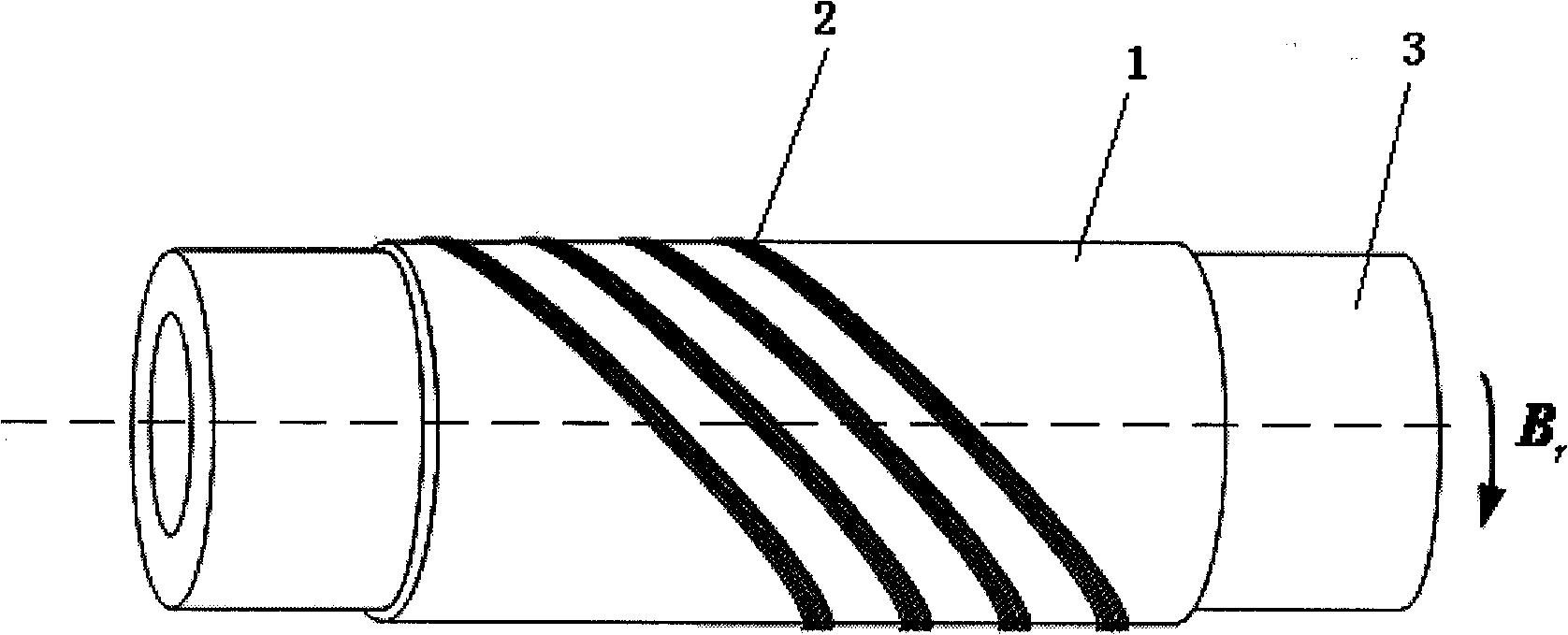
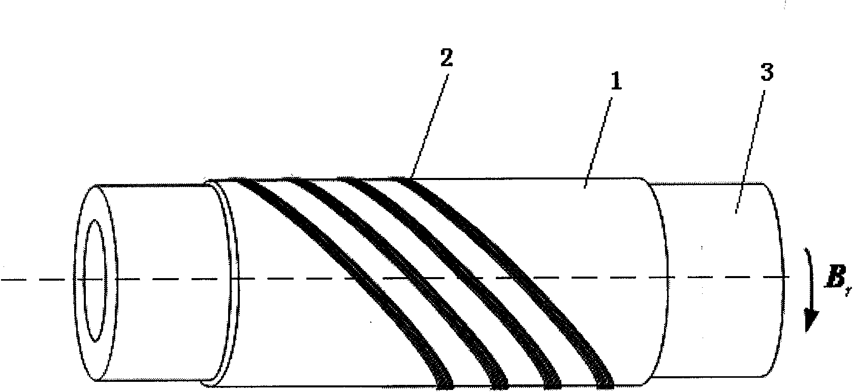
[0018] As shown in Fig. 1 and Fig. 2, the present invention includes a pre-magnetized nickel-iron alloy sheet 1 and multiple groups of coil strips 2, wherein:

[0019] The nickel-iron alloy sheet 1 is rectangular, and is magnetized along one side to form a pre-magnetized nickel-iron alloy sheet, so that the nickel-iron alloy sheet 1 has a static bias magnetic field. Then the nickel-iron alloy sheet 1 is tightly fixed on the outer wall of the pipeline to be tested 3 along the circumferential direction of the pipeline to be tested 3, so that the residual magnetic flux density B on the nickel-iron alloy sheet 1 is r distributed along the circumferential direction of the pipeline 3 to be tested.

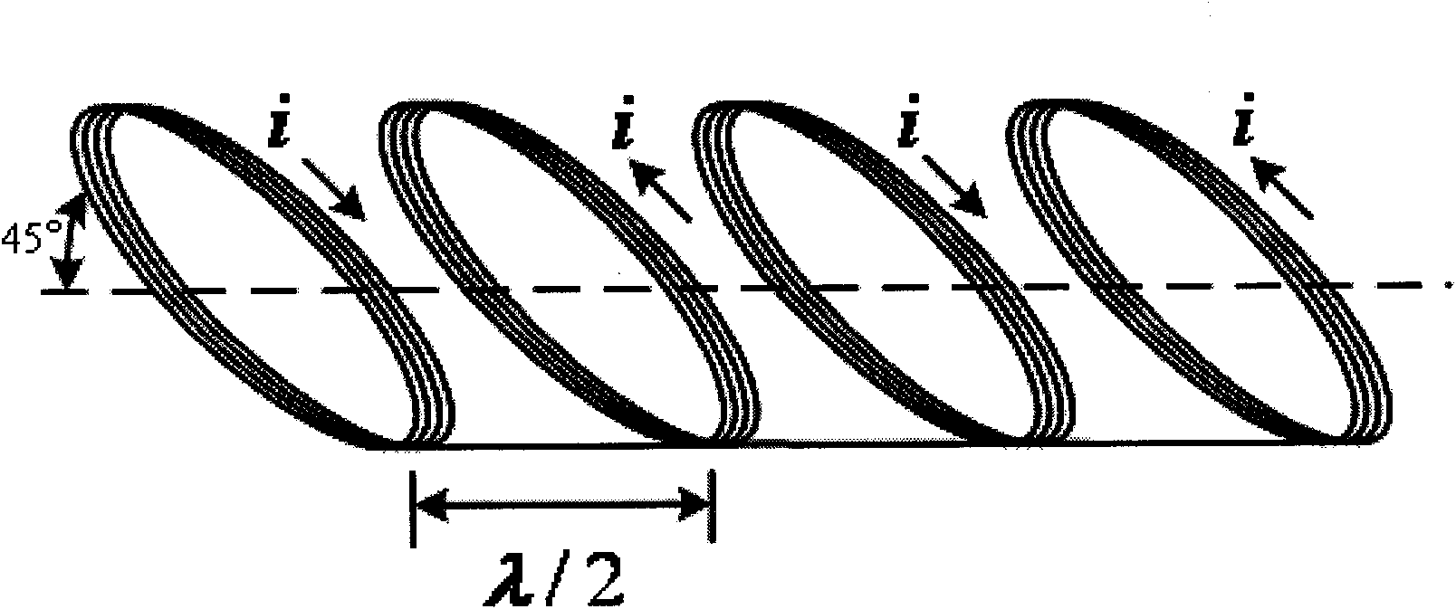
[0020] The multi-group coil strip 2 is a multi-group coil formed by winding a wire on the pre-magnetized nickel-iron alloy sheet 1 fixed on the outer wall of t...


PUM

PropertyMeasurementUnit
thicknessaaaaaaaaaa

Abstract

The invention relates to a pipeline axial ultrasonic guided wave energy exchange probe, which is characterized in that the pipeline axial ultrasonic guided wave energy exchange probe comprises a premagnetized nickel-iron alloy sheet and a plurality of groups of coil belts, wherein the nickel-iron alloy sheet is tightly fixed on the outer wall of a pipeline to be detected in the circumferential direction of the pipeline to be detected, the rest magnetic flux density on the nickel-iron alloy sheet is distributed along the circumferential direction of the pipeline to be detected, a plurality of groups of coil belts are a plurality of groups of coil belts formed by winding a conducting wire on the premagnetized nickel-iron alloy fixed on the outer wall of the pipeline to be detected, the two adjacent groups of coils have the same center distance, and in addition, the two adjacent groups of coils have the opposite winding directions. A pulse power amplifier is connected with the starting end of the conducting wire for winding a plurality of groups of coil belts, and the tail end of the conducting wire for winding a plurality of groups of coil belts is sequentially connected with a wave filter amplification circuit and an oscilloscope. The invention can be widely applied to the field of nondestructive detection of the pipeline.

Description

technical field [0001] The invention relates to a pipeline non-destructive testing device, in particular to a pipeline axial ultrasonic guided wave transducer probe used in the pipeline non-destructive testing device. Background technique [0002] It is an effective way to use axial ultrasonic guided waves to detect defects such as welds and circumferential cracks on the pipeline to be tested. The existing ultrasonic transducers for exciting and receiving axial ultrasonic guided waves generally use piezoelectric transducers. Its detection principle is: when the axial ultrasonic guided wave propagates in the pipeline to be tested and encounters a weld or a circumferential crack on the pipeline to be tested, the axial ultrasonic guided wave is reflected immediately, and the excitation of the axial ultrasonic guided wave The end receives the reflected axial ultrasonic guided wave, and calculates the product of the time difference between excitation and reception of the axial ul...

Claims


Application Information

Patent Timeline
Patent Type & Authority Applications(China)
IPC IPC(8): G01N29/24G01N29/04F17D5/00
Inventor 黄松岭赵伟郝宽胜王珅董甲瑞童允魏争李鹏崔爱芳许鹏
Owner TSINGHUA UNIV
Why Eureka
Try Eureka