High-density multiple-wavelength optical time domain reflectometer
An optical time domain reflection, high-density technology, used in electromagnetic wave transmission systems, electrical components, transmission systems, etc., can solve problems such as the inability to individually identify divergent fiber optic networks, improve maintenance efficiency, mass monitoring, and ensure reliability and stability. sexual effect
- Summary
- Abstract
- Description
- Claims
- Application Information
AI Technical Summary
Problems solved by technology
Method used
Image

Examples
Embodiment
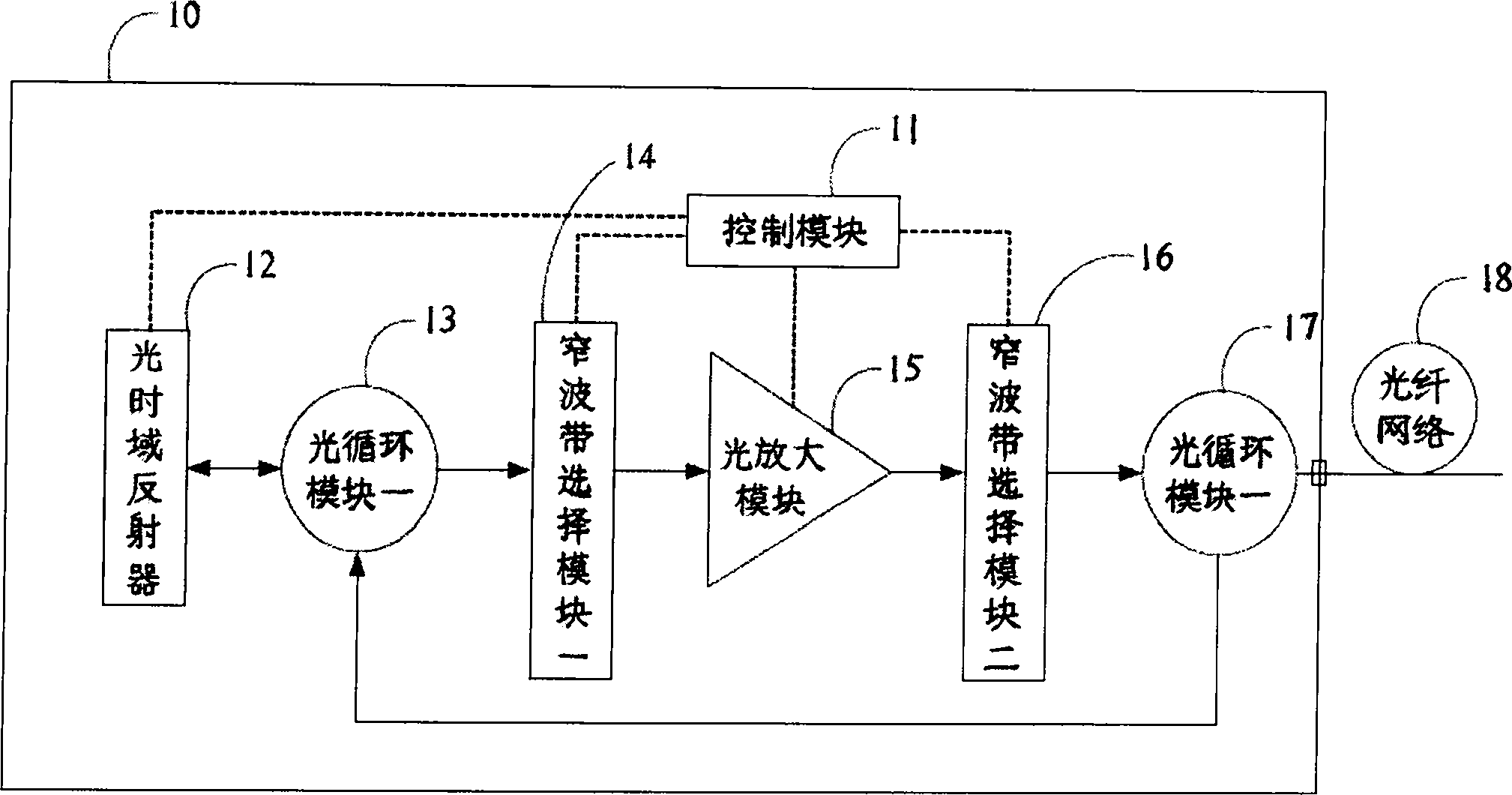
[0016] The present invention is a device for measuring or monitoring the normal state of the optical fiber at any position on the optical fiber network. Compared with the function of the traditional optical time domain reflector, the present invention can provide higher density, more wavelengths, and more flexible Applications.
[0017] Please refer to FIG. 1 , which is a schematic diagram of the structure of the high-density multi-wavelength optical time domain reflector of the present invention. The high-density multi-wavelength optical time domain reflector 10 of the present invention is mainly controlled by a control module 11 . According to the specified requirements, the optical time domain reflector 12 is controlled to send out the wide-band measurement light wave, which is guided into the narrow-band selection module 14 through the optical loop module 13 . Wherein only the wavelength of the specified narrow band can be converted and enter the optical amplification mod...
no. 1 example
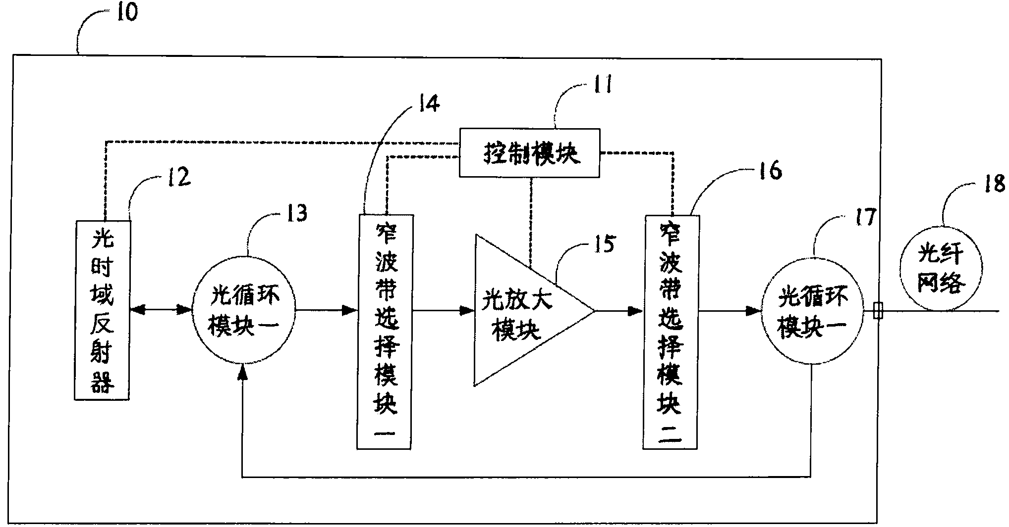
[0020] Please refer to Fig. 2, which is the first embodiment diagram of the narrow-band selection module of the high-density multi-wavelength optical time domain reflector of the present invention, wherein the narrow-band selection modules one 14 and two 16 are high-density wavelength division multiplexing module and optical path selection module. The high-density multi-wavelength optical time-domain reflector 10 of the present invention is controlled by the control module 11, and according to the specified requirements, the optical time-domain reflector 12 is controlled to send out wide-band measurement light waves, which are introduced into the high-density analytical light wave through the optical cycle module-13. The wave multitasking module one 141 can cut the broadband light wave into multiple narrow-band light waves, and through the optical path selection module one 142, only the specified narrow-band light wave will be switched out to enter the optical amplification mod...
no. 2 example
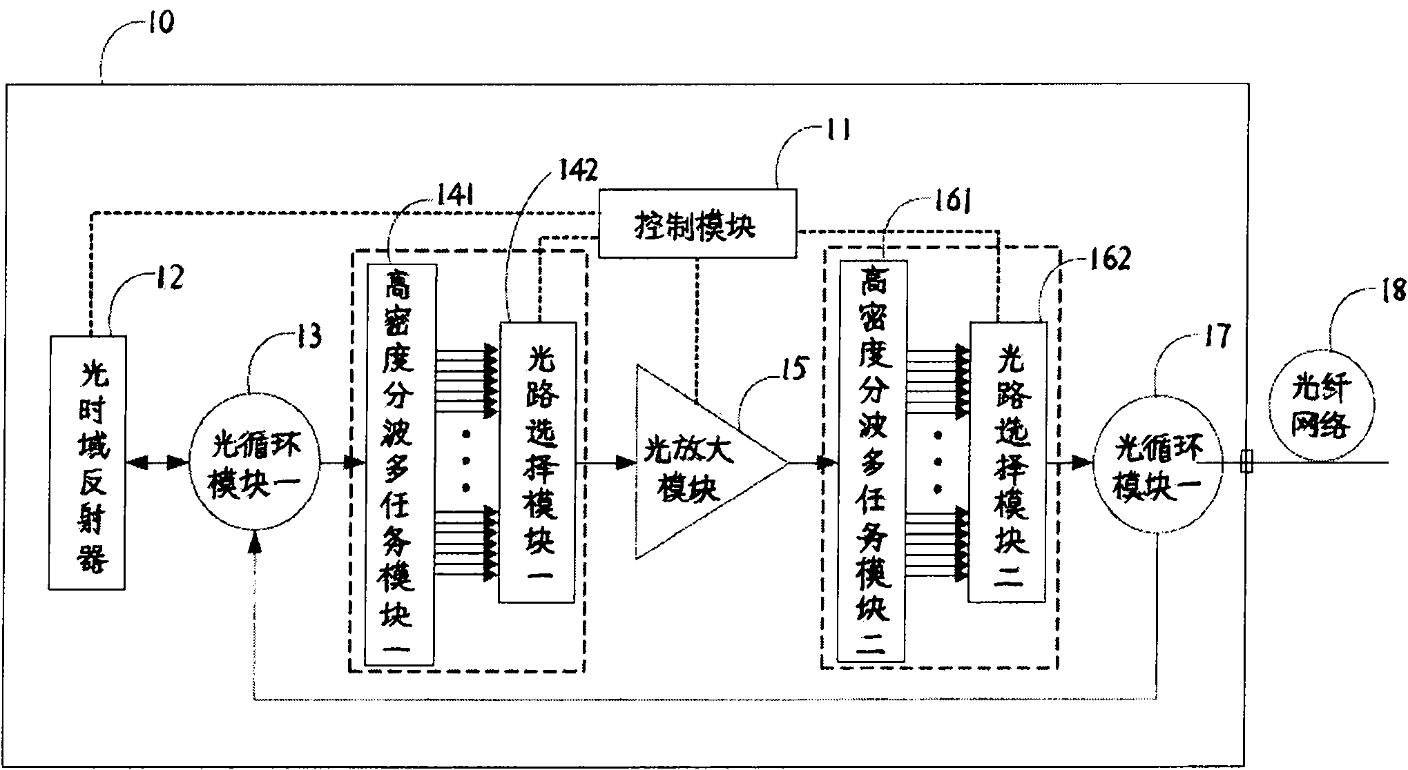
[0022] Please refer to Fig. 3, which is the second embodiment diagram of the narrowband selection module of the high-density multi-wavelength optical time domain reflector of the present invention, wherein the narrowband selection module one 14 is two groups of high-density wave division multitasking modules The narrowband selection module 2 16 is composed of a high-density wavelength division multitasking module and an optical path selection module. The high-density multi-wavelength optical time-domain reflector 10 of the present invention is controlled by the control module 11, and according to the specified requirements, the optical time-domain reflector 12 is controlled to send out wide-band measurement light waves, which are introduced into the high-density analytical light wave through the optical cycle module-13. Wave multi-tasking module 1 141 can cut broadband light waves into multiple narrow-band light waves, which are respectively connected with high-density wave-div...
PUM
 Abstract
Description
Claims
Application Information
 - R&D
- Intellectual Property
- Life Sciences
- Materials
- Tech Scout
- Unparalleled Data Quality
- Higher Quality Content
- 60% Fewer Hallucinations
Browse by: Latest US Patents, China's latest patents, Technical Efficacy Thesaurus, Application Domain, Technology Topic, Popular Technical Reports.
© 2025 PatSnap. All rights reserved.Legal|Privacy policy|Modern Slavery Act Transparency Statement|Sitemap|About US| Contact US: help@patsnap.com