Piston pump for conveying a fluid and associated braking system

A technique for piston pumps and piston parts, which is applied to components of pumping devices for elastic fluids, brakes, liquid fuel engines, etc., can solve problems such as weakening strength, and achieve reduced component loads, favorable costs, and the most structural space good effect

Active Publication Date: 2010-08-25
ROBERT BOSCH GMBH
View PDF0 Cites 1 Cited by
  • Summary
  • Abstract
  • Description
  • Claims
  • Application Information

AI Technical Summary

Problems solved by technology

The second piston part 2.2, which is designed as a valve seat, is therefore made of a stable part, preferably a metal part, and can only be weakened by the influence of the suction hole in the form of the transverse hole 3

Method used


Image

  • Piston pump for conveying a fluid and associated braking system
  • Piston pump for conveying a fluid and associated braking system
  • Piston pump for conveying a fluid and associated braking system

Examples


Embodiment Construction

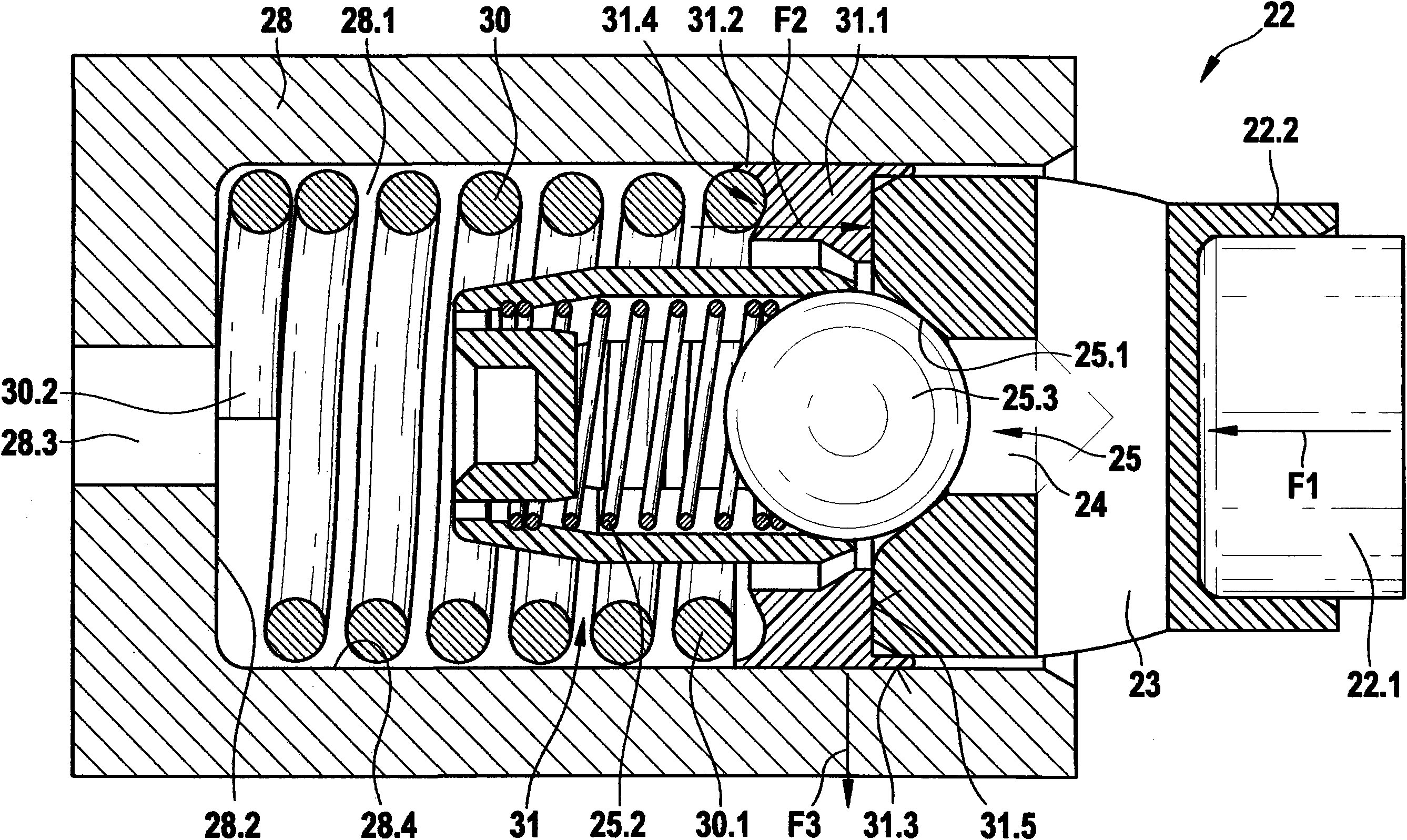
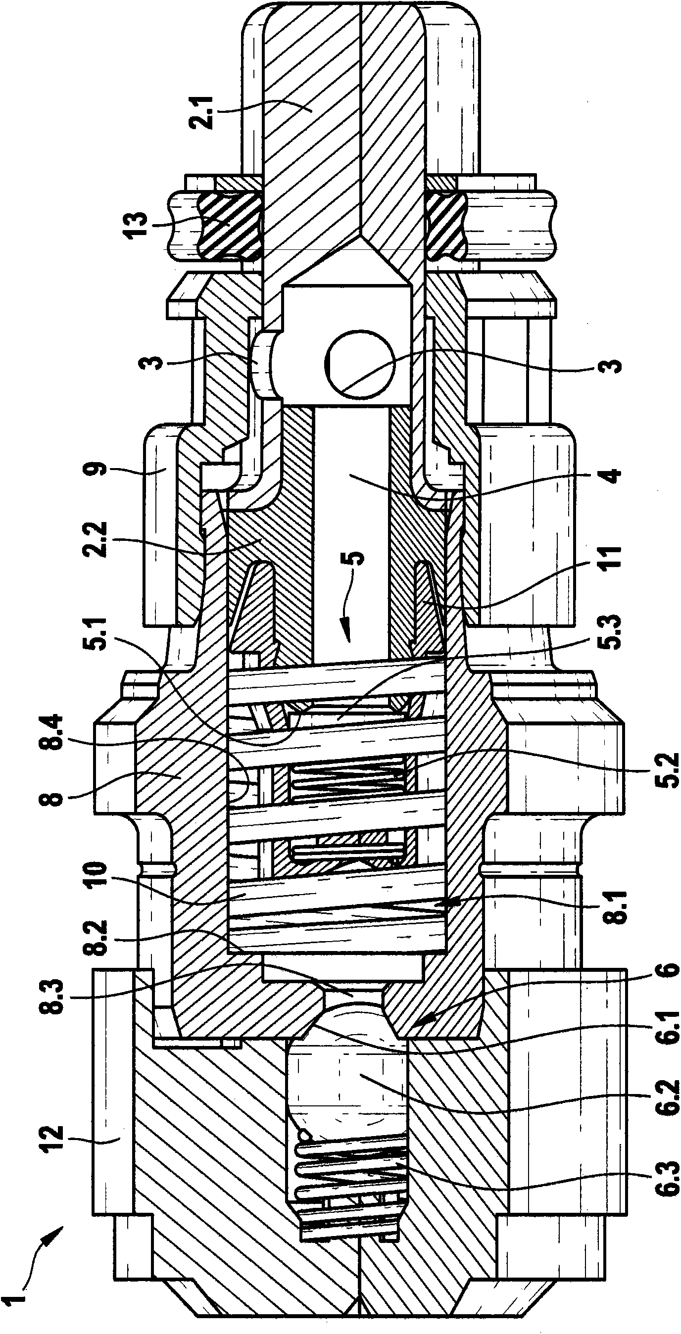
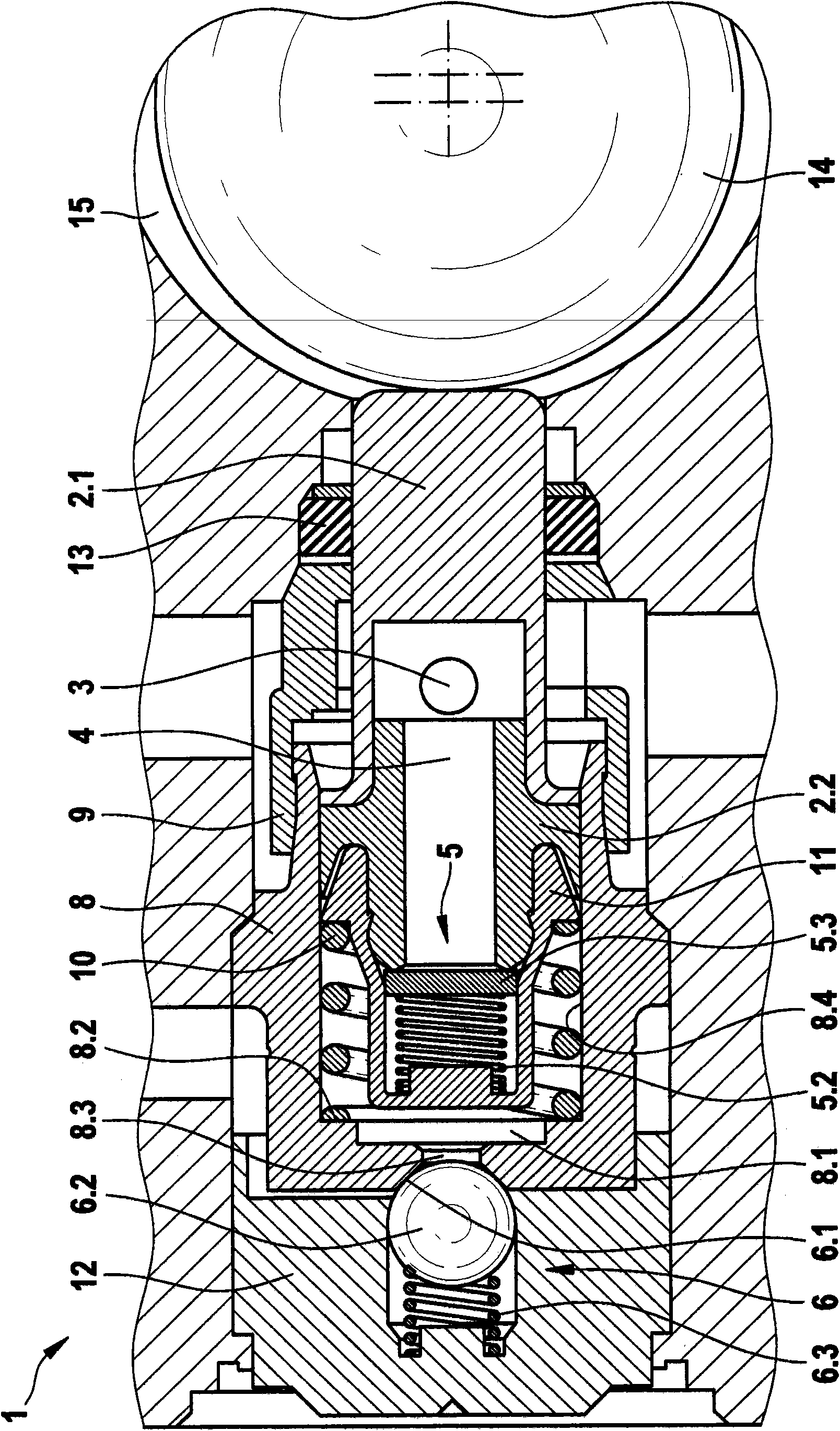
[0016] The piston pump according to the invention, which can be used as a return pump in a vehicle brake system, essentially comprises the same components as the conventional piston pump 1 described with reference to FIGS. 1 to 3 . Therefore, in order to avoid repetition, only the main differences of the piston pump according to the invention from the conventional piston pump 1 according to FIGS. 1 to 3 will be described in detail here. Unlike the conventional piston pump 1 according to FIGS. 1 to 3, the piston pump according to the invention comprises a modified inlet valve in combination with a modified piston assembly.

[0017] As shown in FIG. 4, similar to the conventional piston pump 1, the inlet valve 25 of the piston pump according to the invention comprises a cage 31 and a corresponding inlet valve seat 25.1, in which the inlet valve spring 25.2 and for example An inlet valve seal 25.3 consisting of a sealing ball, an inlet valve seat 25.1 is arranged on the second pi...


PUM


Abstract

The invention relates to a piston pump having a piston assembly (22), comprising at least one cross bore (23) and a longitudinal bore (24) corresponding to the at least one cross bore (23), a cylinder (28), into which the piston assembly (22) is guided in a longitudinally movable manner, and an inlet valve (25) comprising a cage element (31), in which an inlet valve spring (25.2) and an inlet valve sealing element (25.3) are disposed, and a corresponding inlet valve seat (25.1), which is disposed on the piston assembly (22), wherein the inlet valve sealing element (25.3) can be pushed into the corresponding inlet valve seat (25.1) in a sealing manner by a spring force of the inlet valve spring (25.2) in order to close the longitudinal bore (24), wherein fluid can be drawn in via the at least one cross bore (23) disposed in the piston assembly (22); said fluid can be guided through the longitudinal bore (24) into a compression chamber (28.1) via the inlet valve (25); a return spring (30) is disposed in the compression chamber for the piston assembly (22). The invention further relates to an associated braking system. The cage element (31) has a resilient high-pressure sealing element (31.1) that is configured to receive radially acting power components, and to effect a seal against a cylinder wall (28.4) via a radial sealing surface (31.3), and in order to effect an axial seal against the piston assembly (22) via an axial sealing surface (31.5).

Description

technical field [0001] The invention relates to a piston pump for conveying fluids according to the preamble of independent claim 1, which is used in particular in a brake system of a motor vehicle. Background technique [0002] This type of piston pump is preferably used as a return pump in vehicles with hydraulic or electrohydraulic vehicle braking systems for selectively lowering or raising the brake pressure in the wheel brake cylinders, whereby the wheel brakes can be adjusted brake pressure in the cylinder. Such regulation can be carried out, for example, in an antilock brake system (ABS), an anti-skid control system (ASR system), a driving dynamics control system, or the like. 1 to 3 show conventional piston pumps, which are used in vehicle braking systems. As shown in Figures 1 to 3, a traditional piston pump 1 includes a piston assembly 2, an inlet valve 5, an outlet valve 6 and a cylinder 8, the piston assembly has a first piston part 2.1 and a second piston part...

Claims


Application Information

Patent Timeline
Patent Type & Authority Applications(China)
IPC IPC(8): F04B1/04F04B53/10
CPCF04B1/0452F04B53/10B60T8/4031F04B53/126F04B53/146
Inventor H·雅恩M·齐默尔曼
Owner ROBERT BOSCH GMBH
Why Eureka
Try Eureka