Separated full-automatic drilling and riveting bracket system

An automatic drilling and riveting machine, fully automatic technology, applied to other manufacturing equipment/tools, large fixed members, metal processing machinery parts, etc., can solve the center of gravity deviation of the X-axis sliding table, difficult installation and debugging, large footprint, etc. problems, to achieve the effect of reducing installation height, good production continuity and high degree of automation

Inactive Publication Date: 2010-09-01
CHENGDU AIRCRAFT INDUSTRY GROUP
View PDF5 Cites 22 Cited by
  • Summary
  • Abstract
  • Description
  • Claims
  • Application Information

AI Technical Summary

Problems solved by technology

These three types of automatic drilling and riveting bracket systems have their own advantages and disadvantages: although the structure of the suspended fully soft semi-automatic drilling and riveting bracket system is simple and the cost is low, it cannot achieve precise positioning and automatic drilling and riveting; the suspended semi-rigid automatic bracket system The positioning is more accurate, but the rigidity and stability are poor. It can only realize automatic drilling and riveting within a single stringer. Manual adjustment is required for drilling and riveting across stringers. Only semi-automatic drilling and riveting can be realized. The continuity of riveting work is poor and the production eff...

Method used


Image

  • Separated full-automatic drilling and riveting bracket system
  • Separated full-automatic drilling and riveting bracket system
  • Separated full-automatic drilling and riveting bracket system

Examples


Embodiment Construction

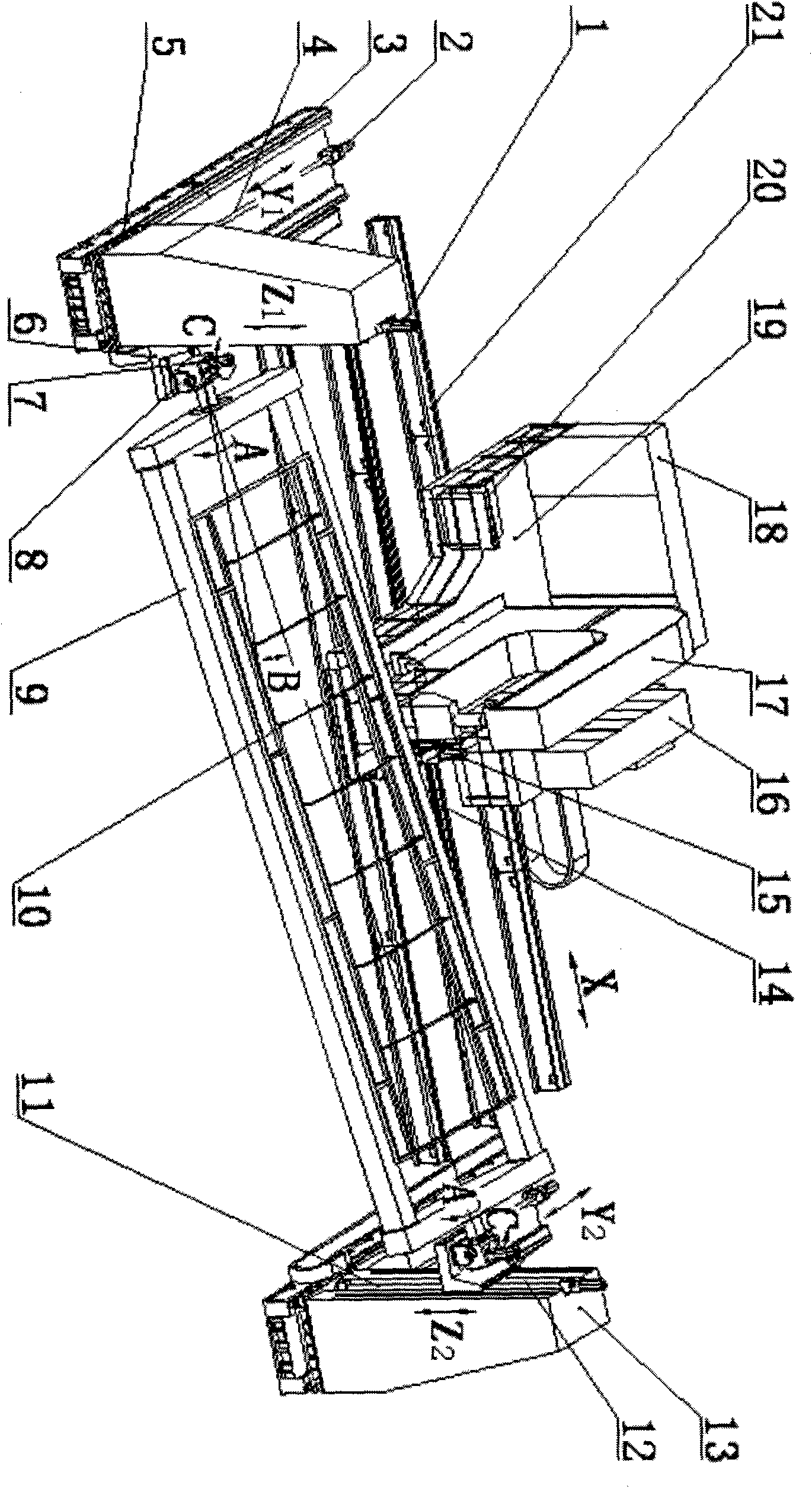
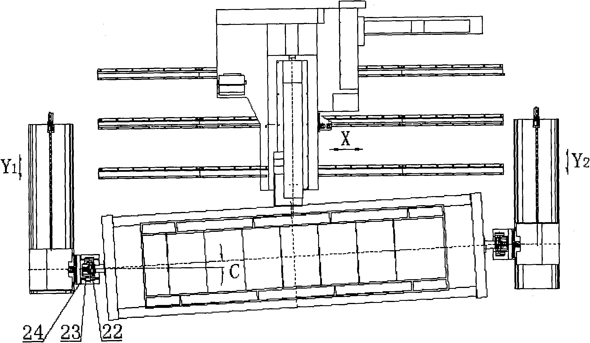
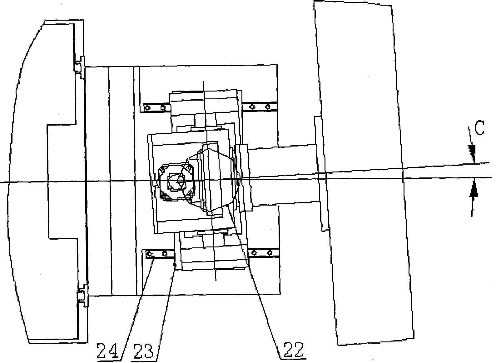
[0018] refer to figure 1 , figure 2 , image 3 , set forth as follows with regard to implementing an embodiment of the present invention:

[0019] The automatic drilling and riveting machine 17, the operating table 20, the control cabinet 18, the automatic nail feeding mechanism 16, and the X-axis motor 15 are installed on the X-sliding table 19, carried and guided by the X-axis guide rail 21, and the rack 14 is driven by the X-axis motor 15 , to form X-axis motion; two Z columns 13 are installed on the Y slides 5 on the left and right sides, the Y-axis screw 4 is driven by the Y-axis motor 2, carried and guided by the Y-axis guide rail 3, and the Y slide 5 is driven to form the Y-axis Movement; the Z sliding table 6 is guided by the Z-axis guide rails 11 installed on the Z columns 13 on the left and right sides, the support frame 9 is installed on the Z sliding table 6, and the Z-axis motor 1 drives the Z-axis screw rod 12 to drive the Z Slide table 6 moves up and down to...


PUM


Abstract

The invention relates to a s full-automatic drilling and riveting bracket system, comprising a lateral X-axis guide rail , a slipway X, a drilling and riveting machine, a console, a longitudinal Y-axis guide rail, a left-right slipway Y, a Z pillar arranged on the slipway Y, a Z slipway, a bracket frame arranged on the slipway Z, a working frame fixed on the bracket frame and on the like. The motion of an axis A is achieved by the rotation of the bracket frame, the motion of an axis B is achieved by a differential motion of Z1 and Z2, and the motion of an axis C is achieved by a differential motion of Y1 and Y2. The location and normal adjustment of parts are realized by the together motion of six coordinate axis including an X-axis, a Y-axis, a Z-axis, an A-axis, a B-axis and a C-axis. The invention has simple structure, stable quality of riveting and high precision of positioning, can produce different kinds of parts on the same bracket system; the operation of clamping and adjusting a product is very convenient because the bracket frame can be lowered to a lower height. The invention can realize cross-stringer automatic drilling and riveting; has good production continuity, high degree of automation, small occupation area and low manufacture cost, and the machining efficiency reaches the most advanced world level.

Description

technical field [0001] The invention relates to a drilling and riveting bracket, in particular to a separate fully automatic drilling and riveting bracket system for automatic drilling and riveting assembly of thin-walled sheet metal parts and components. Background technique [0002] The automatic drilling and riveting bracket system is a product integrating machine, electricity and hydraulics. The movement of the automatic drilling and riveting bracket is controlled by the numerical control system to realize automatic positioning, clamping, and normal adjustment of thin-walled sheet metal parts. Drilling and riveting machine, realize the functions of automatic hole making (sinking), gluing, nail feeding, milling and other functions of thin-walled sheet metal parts and components. In the prior art, there are three main structures of the drilling and riveting bracket system: a suspended fully soft-hanging semi-automatic drilling and riveting bracket system, a suspended semi-...

Claims


Application Information

Patent Timeline
IPC IPC(8): B23Q1/25B23P23/02
Inventor 余泽黄中平李国进
Owner CHENGDU AIRCRAFT INDUSTRY GROUP
Why Eureka
Try Eureka