Probe grinding machine of wheel speed sensor

A wheel speed sensor and grinding machine technology, applied in grinding machines, grinding/polishing equipment, metal processing equipment, etc., can solve the problems of difficult control of product accuracy, high labor intensity of workers, and product scrapping, so as to reduce product scrapping rate, The effect of high work efficiency and high processing precision

Inactive Publication Date: 2010-09-01
杭州南科汽车传感器有限公司
View PDF4 Cites 8 Cited by
  • Summary
  • Abstract
  • Description
  • Claims
  • Application Information

AI Technical Summary

Problems solved by technology

The left end of the insulating shell needs to be connected to the wheel hub, and the extension distance of the left end of the insulating shell including the iron core directly affects the sensing performance of the wheel speed sensor. Therefore, after the wheel speed sensor is manufactured, secondary processing is required, and the left end of the insulating

Method used


Image

  • Probe grinding machine of wheel speed sensor
  • Probe grinding machine of wheel speed sensor
  • Probe grinding machine of wheel speed sensor

Examples


Embodiment 1

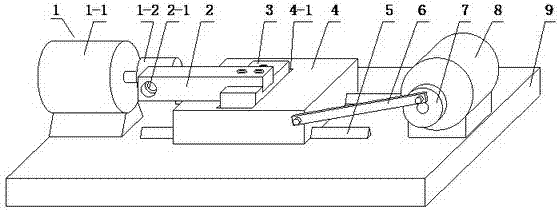
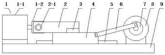
[0022] Embodiment 1: refer to Figure 1~7 . A probe grinding machine for a wheel speed sensor, the probe grinding machine includes a grinder 1, a frame 9, a transverse guide rail 5, a supporting plate 4, a probe frame, a connecting rod 6, an eccentric wheel 7 and a motor 8, and the upper end of the frame 9 is provided with a transverse guide rail 5. There is a guide groove 4-2 under the supporting plate 4, and the supporting plate 4 cooperates with the transverse guide rail 5 through the guide groove 4-2, and the supporting plate 4 can slide left and right along the transverse guide rail 5, and the grinder 1 is located on the supporting plate 4 On the left side, the motor 8 is positioned at the right side of the supporting plate 4, the power output direction of the motor 8 is perpendicular to the transverse guide rail 5, the front end of the power output shaft of the motor 8 is connected with the eccentric wheel 7, and the two ends of the connecting rod 6 are connected with th...

Embodiment 2

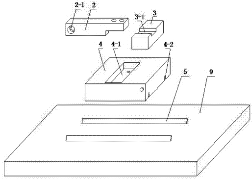
[0023] Embodiment 2: refer to figure 1 , 2 , 3, 6 and 7. The probe frame is composed of an adjustment block 3 and a probe matching block 2. The upper end of the supporting plate 4 is provided with an adjustment groove 4-1. The adjustment block 3 is located in the adjustment groove 4-1 and is fixed to each other by bolts. The right end of the probe matching block 2 is connected to the adjustment The block 3 is connected, and its left end is provided with a matching hole 2-1 for installing the sensor probe 11.

Embodiment 3

[0024] Embodiment 3: refer to Figure 4 and 5 . On the basis of Embodiment 1 and Embodiment 2, the upper end of the supporting plate 4 is provided with a longitudinal guide rail 10, the lower end of the adjustment block 3 is provided with a guide groove I3-2 and the guide groove I3-2 cooperates with the longitudinal guide rail 10, and the adjustment block 3 3. The slide can be adjusted back and forth along the longitudinal guide rail 10.


PUM


Abstract

The invention relates to a grinding device, in particular to a probe grinding machine of a wheel speed sensor. The probe grinding machine comprises a grinding wheel machine, a stander, a transverse guide rail, a support plate, a probe rack, a connecting rod, an eccentric wheel and a motor, wherein the upper end of the stander is provided with the transverse guide rail; a guide groove is positioned under the support plate; the support plate is matched with the transverse guide rail by the guide rail and can slide at the left and the right along the transverse guide rail; the grinding wheel machine is positioned at the left side of the support plate, and thetor is arranged at the right side thereof; the power output direction of the motor is vertical to the transverse guide rail; the front end of a power output shaft of the motor is connected with the eccentric wheel; the two ends of the connecting rod are respectively articulated with the eccentric wheel and the support plate; and the right end of the probe rack is connected with the support plate, and the left end thereof is positioned at the outer side of a grinding wheel of the grinding wheel machine. The probe grinding machine has the advantages that the machine has reasonable structure, simple operation, safety and reliability as well as high working efficiency, can realize batch processing of products, is high in processing accuracy, and effectively reduces the rejection rate of the products.

Description

technical field [0001] The invention relates to a grinding device, in particular to a probe grinding machine for a wheel speed sensor. Background technique [0002] At present, the active wheel speed sensor includes an insulating shell, and the insulating shell is equipped with a skeleton, a magnetic core, an induction coil and a magnetic steel. The magnetic core, the induction coil, and the magnetic steel are respectively connected to the skeleton, and the iron core and the magnetic steel are from left to The right ones are installed inside the frame one by one, one end of the iron core is exposed outside the insulating shell, the other end is connected to the magnetic steel, and the induction coil is wound outside the frame close to the iron core. The left end of the insulating shell needs to be connected to the wheel hub, and the extension distance of the left end of the insulating shell including the iron core directly affects the sensing performance of the wheel speed s...

Claims


Application Information

Patent Timeline
IPC IPC(8): B24B19/00
Inventor 万国强万国彪张鸿
Owner 杭州南科汽车传感器有限公司
Why Eureka
Try Eureka