Hydrophilic material surface super hydrophobic functional shift micro structure design method

A design method and technology for hydrophilic materials, which can be used in microstructure technology, microstructure devices, nanostructure manufacturing, etc., can solve the problems of difficult to achieve superhydrophobicity on the surface of hydrophilic materials, difficult to achieve superhydrophobicity, etc., and achieve surface performance. stable effect

Inactive Publication Date: 2010-09-01
JIANGSU UNIV
View PDF3 Cites 20 Cited by
  • Summary
  • Abstract
  • Description
  • Claims
  • Application Information

AI Technical Summary

Problems solved by technology

Therefore, superhydrophobic properties on the surface of hydrophilic materials are difficult to achieve
[0009] In conclusion, the construction of superhydrophobic surfaces on hydrophilic materials is of great significance in realizing non-pollution self-cleaning and antifouling, while general microstructured surfaces formed by hydrophilic materials are difficult to achieve superhydrophobic properties.

Method used


Image

  • Hydrophilic material surface super hydrophobic functional shift micro structure design method
  • Hydrophilic material surface super hydrophobic functional shift micro structure design method
  • Hydrophilic material surface super hydrophobic functional shift micro structure design method

Examples


Embodiment 1

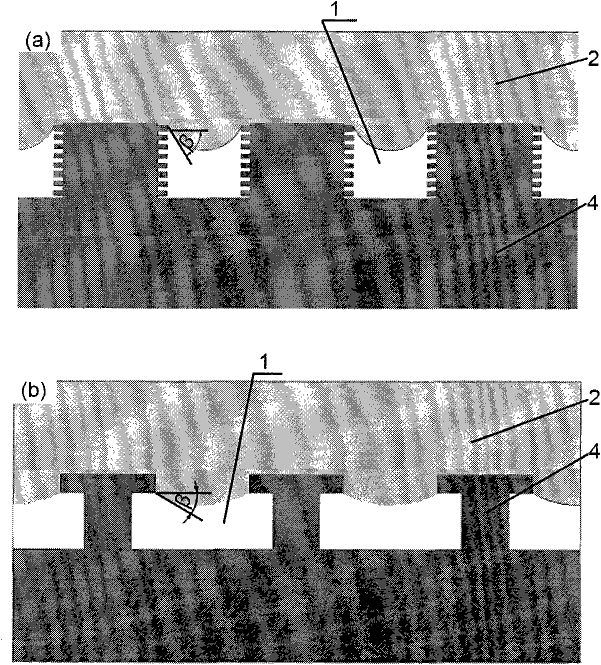
[0026] Embodiment 1 (square column form structure, section structure is figure 2 (a) The structural form, environmental conditions and parameters are: P-P 0 =1kPa, θ=50°, liquid 2 is water, γ=0.072N / m, θ C =150°):

[0027] Calculate the protrusion ratio of the surface 4 of the microstructure of the hydrophilic material according to the Cassie calculation formula. f=(cosθ C +1) / (cosθ+1)=0.08155;

[0028] Square column form, L 1 =L 2 =L,A=(Lf) 2 , S=4Lf, then there is L max 0 )(1-f 2 )]=23.6μm, where L max is the maximum period.

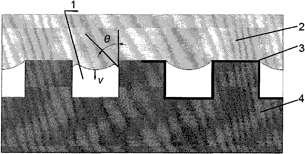
[0029] Select the hydrophilic material microstructure 4 whose structural period is L=1 μm, and calculate the angle β formed between the interface formed by the liquid 2 and air 1 in the microstructure and the microstructure wall, Much smaller than the intrinsic contact angle 50° of liquid water 2 on the surface of the smooth hydrophilic material, therefore, liquid water 2 is in the Cassie contact state on the surface 4 of the microstructur...

Embodiment 2

[0031] Embodiment 2 (square column form structure, section structure is figure 2 (b) The structural form, environmental conditions and parameters are: P-P 0 =10kPa, θ=50°, liquid 2 is water, γ=0.072N / m, θ C =150°):

[0032] Calculate the protrusion ratio of the surface 4 of the microstructure of the hydrophilic material according to the Cassie calculation formula. f=(cosθ C +1) / (cosθ+1)=0.08155;

[0033] Square column form, L 1 = L 2 =L,A=(Lf) 2 , S=4Lf, then there is L max 0 )(1-f 2 )]=23.6μm, where L max is the maximum period.

[0034] Select the hydrophilic material microstructure 4 whose structural period is L=1 μm, and calculate the angle β formed between the interface formed by the liquid 2 and air 1 inside the microstructure and the microstructure wall, Far smaller than the intrinsic contact angle 50° of liquid water 2 on a smooth hydrophilic surface, liquid water 2 is in the Cassie contact state on the surface 4 of the microstructure of the hydrophilic mater...


PUM


Abstract

The invention provides a hydrophilic material super hydrophobic surface micro nano structure design method, relating to the micro nano structure function surface design preparation technical field. Protuberance ratio of micro structure is calculated according to super hydrophobic contact angle requirement; and meanwhile maximum period of micro structure is determined according to use condition; and finally, contact status of liquid and micro structure surface is verified according to the designed micro structure and structure parameter. The invention realizes surface super hydrophobic performance by controlling the form of micro structure without carrying out coating treatment on the surface, thus the super hydrophobic performance of micro structure surface can not be influenced when the structure form of the interior of micro structure is not changed even if the material is partially abrased, super hydrophobic surface has stable performance, and the performance is effective for long term.

Description

technical field [0001] The invention relates to the technical field of micro-nano structure functional surface design and preparation, in particular to a surface structure design method for designing a new structure to achieve super-hydrophobic properties on the surface of hydrophilic materials, which is suitable for self-cleaning and antifouling requirements and requiring surface materials to be non-toxic Design and analysis of superhydrophobic surface structure in the case of coating materials. Background technique [0002] Superhydrophobic surface refers to the surface on which water droplets present a large contact angle (θ > 150°) on the surface. Due to its self-cleaning and antifouling effect, it has a wide range of application prospects in industry. At present, the technology of superhydrophobic modification of the surface of hydrophobic materials has been gradually applied to engineering. Part of the superhydrophobic surface modification technology is used in the ...

Claims


Application Information

Patent Timeline
Patent Type & Authority Applications(China)
IPC IPC(8): B82B3/00B81C99/00
Inventor 周明李健蔡兰
Owner JIANGSU UNIV
Why Eureka
Try Eureka