
Object-oriented cooling device based on pulse tube refrigerator

A pulse tube refrigerator, an object-oriented technology, applied in the field of refrigeration and low temperature, can solve the problems of insufficient heat transfer capacity, limited cooling capacity of refrigerators, large heat transfer temperature difference, etc., to simplify the heat transfer process, improve cooling efficiency, reduce The effect of small heat transfer temperature differences

Inactive Publication Date: 2010-09-01
ZHEJIANG UNIV
View PDF5 Cites 0 Cited by
  • Summary
  • Abstract
  • Description
  • Claims
  • Application Information

AI Technical Summary

Problems solved by technology

Limited by the structure of the refrigerator, the contact area between the cold head of the refrigerator and the cooled device is usually small, so its heat transfer capacity is often insufficient. When transferring a certain amount of cold, the contact area between the cold head of the refrigerator and the cooled device The heat transfer temperature difference (thermal resistance) will be relatively large, which limits the cooling output of the refrigerator to a certain extent
At the same time, because the materials in the cryogenic refrigerator will be affected by the magnetic field to reduce performance, and in order to avoid problems such as mechanical vibration of the cryogenic refrigerator, in many applications, the cryogenic refrigerator is often required to be far away from the object to be cooled, thereby further reducing the temperature of the cryogenic refrigerator. machine cooling effect

Method used


Image

  • Object-oriented cooling device based on pulse tube refrigerator
  • Object-oriented cooling device based on pulse tube refrigerator
  • Object-oriented cooling device based on pulse tube refrigerator

Examples


Embodiment Construction

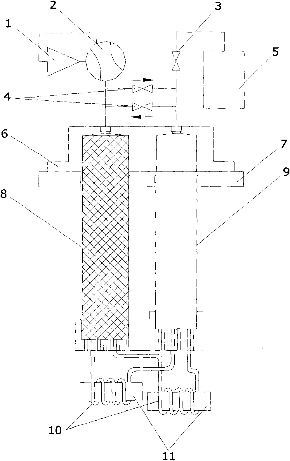
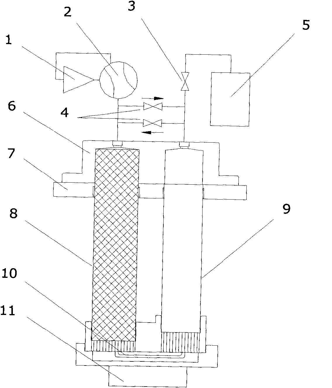
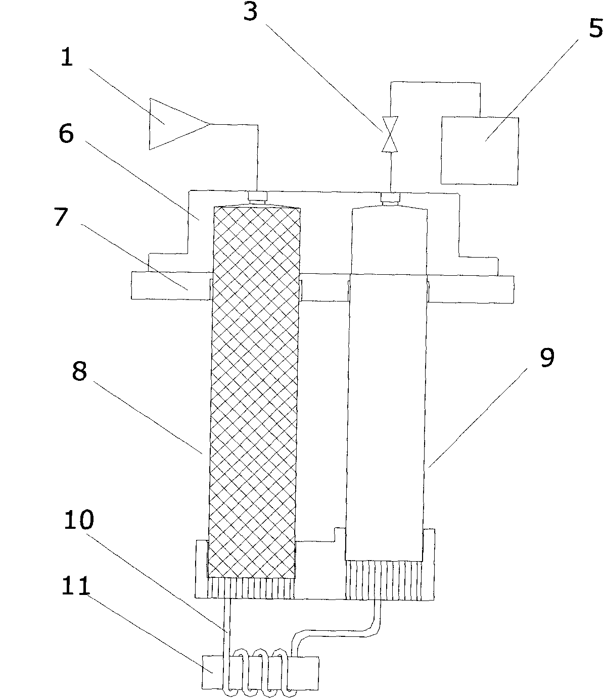
[0019] As shown in the figure, the object-oriented cooling device based on the pulse tube refrigerator includes a compressor 1, a rotary valve 2, an orifice valve 3, a two-way inlet valve 4, an air reservoir 5, a cover 6, a flange 7, and a regenerator 8. The pulse tube 9, the cold head connection coil 10, the cooled device 11, the compressor 1 is connected with the rotary valve 2, and the rotary valve 2 is respectively connected with the hot end of the regenerator 8 and one end of the two-way intake valve 4, The gas storage 5 is respectively connected to the hot end of the pulse tube 9 and the other end of the two-way intake valve 4 through the small hole valve 3 , and the regenerator 8 and the cold end of the pulse tube 9 are connected by a cold head connection coil 10 .

[0020] The pulse tube refrigerator is a GM type pulse tube refrigerator or a Stirling type pulse tube refrigerator. The drive mode of the compressor 1 is electric drive or heat energy drive. The cold head ...


PUM


Abstract

The invention discloses an object-oriented cooling device based on a pulse tube refrigerator, comprising a compressor, a rotary valve, an orifice valve, a two-way intake valve, an air reservoir, a close over, a flange, a heat regenerator, a pulse tube, a cold finger connection coiler and a device to be cooled, wherein the compressor is connected with the rotary valve which is respectively connected with the hot end of the heat regenerator and one end of the two-way intake valve, the air reservoir is respectively connected with the hot end of the pulse tube and the other end of the two-way intake valve through the orifice valve, and the cold end of the pulse tube and the cold end of the heat regenerator are connected through one or more copper tubes which are respectively coiled or welded on one or more devices to be cooled. The cold finger connection coiler of a refrigerator is directly coiled or welded on the devices to be cooled, thereby the invention enlarges the heat exchange area between the refrigerator cold finger and the devices to be cooled, reduces heat transfer temperature difference and obviously enhances the cooling performance; and the refrigerator can be used for directly cooling a plurality of devices to be cooled simultaneously, thereby enhancing the cooling efficiency of the refrigerator and greatly expanding the application range of the cryogenic refrigerator.

Description

technical field [0001] The invention relates to the technical field of refrigeration and low temperature, in particular to an object-oriented cooling device based on a pulse tube refrigerator. Background technique [0002] Pulse tube refrigerator technology occupies a pivotal position in the field of modern low-temperature refrigeration technology. Because it eliminates the ejector at low temperature, it is more reliable than the traditional G-M refrigerator and Stirling refrigerator, and the maintenance-free running time is greatly extended. Therefore, it is very useful in high-tech fields such as aerospace, military, communications, and superconductivity. Wide application prospects. [0003] The basic principle of the pulse tube refrigerator is to use the high and low pressure gas to charge and deflate the pulse tube cavity to obtain the cooling effect. The function of the regenerator is to accumulate the cold energy obtained in the previous cycle and transfer it to the ...

Claims


Application Information

Patent Timeline
Patent Type & Authority Applications(China)
IPC IPC(8): F25D15/00
Inventor 邱利民董文庆甘智华张楷浩王超
Owner ZHEJIANG UNIV
Learn More