
Rapid heat radiation device

A heat-dissipating device and fast technology, applied in indirect heat exchangers, lighting and heating equipment, cooling/ventilating/heating renovation, etc. The effect of total cost reduction, production process simplification, and material cost reduction

Inactive Publication Date: 2010-09-01
滑志红
View PDF4 Cites 0 Cited by
  • Summary
  • Abstract
  • Description
  • Claims
  • Application Information

AI Technical Summary

Problems solved by technology

The above two methods have the following defects: in the first method, due to structural reasons, there is a closed air cavity on the contact surface between the electronic components and the heat pipe, which hinders the transfer of heat, and the heat cannot be quickly transferred to the fixed section of the heat pipe, and the heat dissipation effect is poor; In the second method, the heat conduction cavity is non-circular. During the vacuuming process, the heat conduction wall is easily deformed, resulting in air leakage, cavity shrinkage, poor heat dissipation, high cost and difficult processing.

Method used


Image

  • Rapid heat radiation device
  • Rapid heat radiation device
  • Rapid heat radiation device

Examples


Embodiment Construction

[0022] The structure and operating principle of the rapid heat dissipation device of the present invention will be further described in detail below in conjunction with the accompanying drawings.

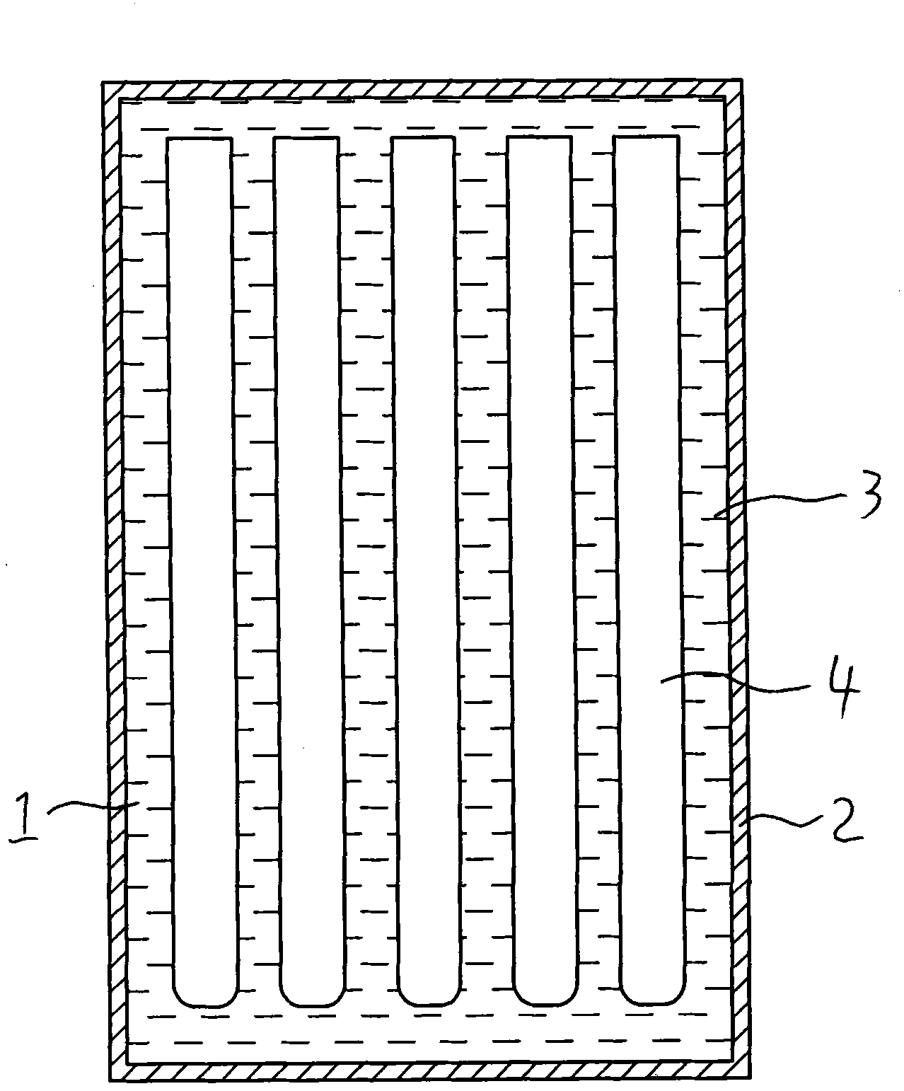
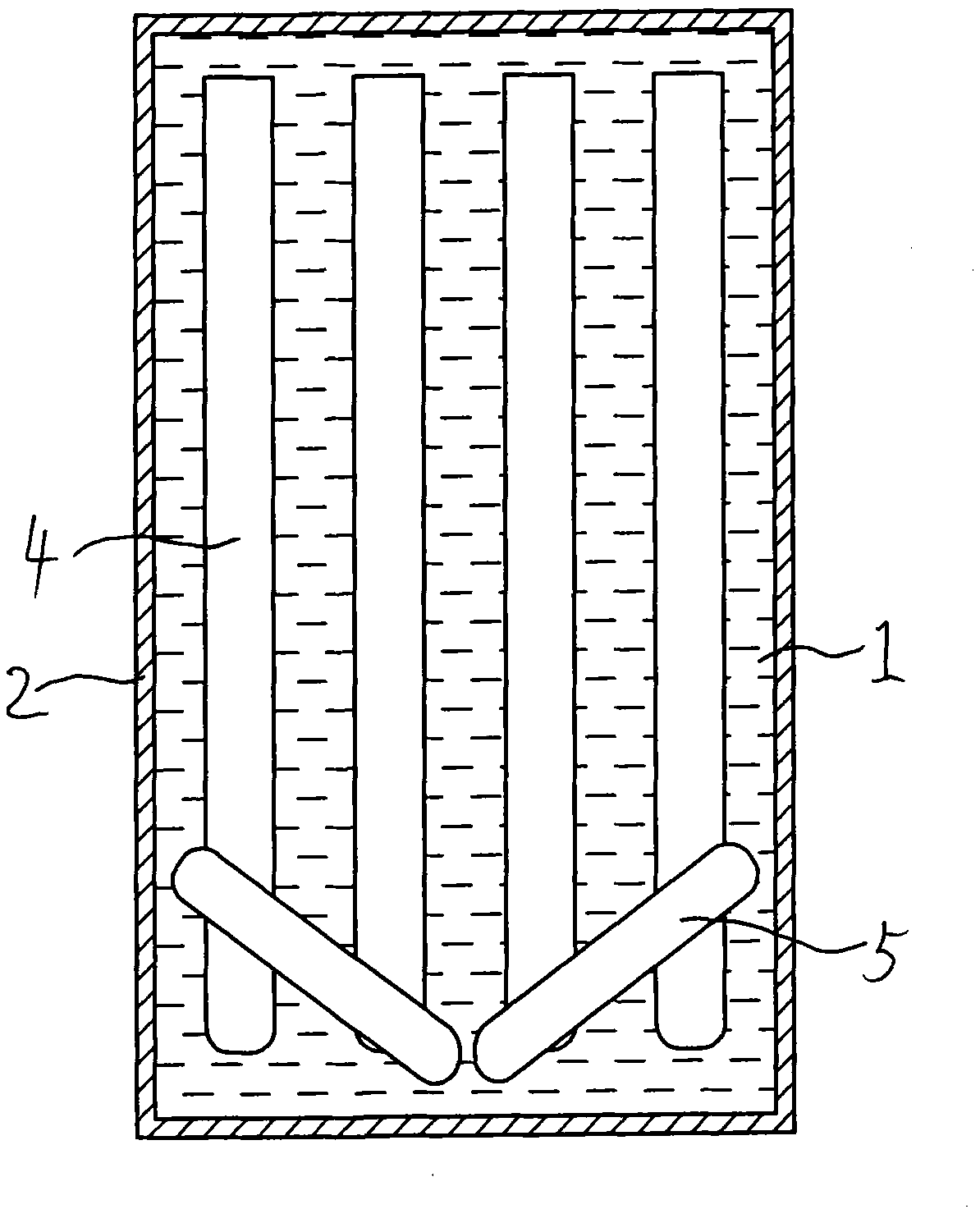
[0023] like figure 1 As shown, the structure schematic diagram of the rapid heat dissipation device of the present invention, the rapid heat dissipation device includes a heat conduction wall 2 made of heat conduction material and a heat conduction cavity 1 surrounded by the heat conduction wall 2, and the heat conduction cavity 1 is filled with liquid heat conduction The medium 3 is provided with a heat pipe 4 in the heat conduction cavity 1 , and the heat pipe 4 is immersed in the liquid heat conduction medium 3 . The electronic components 6 are fixed on the bottom outer surface of the heat conduction wall 2. Since the liquid heat conduction medium 3 is coupled with the heat pipe 4, the heat generated by the electronic components 6 is transferred to the liquid heat conduction medi...


PUM


Abstract

The invention belongs to the technical field of heat radiation devices and discloses a rapid heat radiation device. The rapid heat radiation device is mainly technically characterized by comprising a thermal conductive wall made of thermal conductive materials and a thermal conductive cavity surrounded by the thermal conductive wall, wherein liquid thermal conductive medium is contained in the thermal conductive cavity, a heat pipe is arranged in the thermal conductive cavity, and the heat pipe is immersed in the liquid thermal conductive medium. Heat produced by electronic components is transferred to the liquid thermal conductive medium via the thermal conductive wall, and the liquid thermal conductive medium rapidly transfers the heat to the heat pipe; as the heat pipe has great heat transfer function, the heat is rapidly transferred along the heat pipe; the thermal conductive medium around the heat pipe transfers the heat to the thermal conducive wall for dissipation during the process of transferring the heat along the heat pipe, thereby greatly improving the heat radiation effect; in addition, the thermal conductive cavity does not need to be pumped to vacuum, and the thickness of the thermal conductive wall can be reduced, thereby not only improving the thermal conductive capacity, but also reducing the material cost, greatly simplifying the production process steps and greatly reducing the total production cost.

Description

technical field [0001] The invention belongs to the technical field of heat dissipation devices, in particular to a rapid heat dissipation device. Background technique [0002] For electronic components such as LED lamps that need rapid heat dissipation, the quality of heat dissipation directly affects their service life. At present, the following two methods are mostly used for heat dissipation of electronic components: First, use a fixed section, a heat conduction section, a belt The heat pipe with the heat dissipation section of the heat dissipation fin fixes the electronic components on the fixed section of the heat pipe, and the heat is transferred to the heat dissipation fin of the heat dissipation section through the heat conduction section; secondly, the heat conduction wall of heat conduction material is used to form a plane heat conduction cavity Part of the liquid heat-conducting medium is installed in the heat-conducting cavity, and then the cavity is evacuated t...

Claims


Application Information

Patent Timeline
Patent Type & Authority Applications(China)
IPC IPC(8): H05K7/20F28D15/02
Inventor 滑志红张翔
Owner 滑志红
Learn More