Indoor unit for air conditioner

An air conditioner and indoor unit technology, applied in the field of indoor units, can solve the problems of large-scale indoor units and flying out, and achieve the effect of improving air supply performance

Active Publication Date: 2010-09-01
DAIKIN IND LTD
View PDF3 Cites 6 Cited by
  • Summary
  • Abstract
  • Description
  • Claims
  • Application Information

AI Technical Summary

Problems solved by technology

The water may hit the fan and other structures and fly out of the machine
In addition, there is a problem that the size of the indoor unit is further increased when a heat insulating material is wound around the piping to prevent dew condensation.

Method used


Image

  • Indoor unit for air conditioner
  • Indoor unit for air conditioner
  • Indoor unit for air conditioner

Examples


no. 1 approach

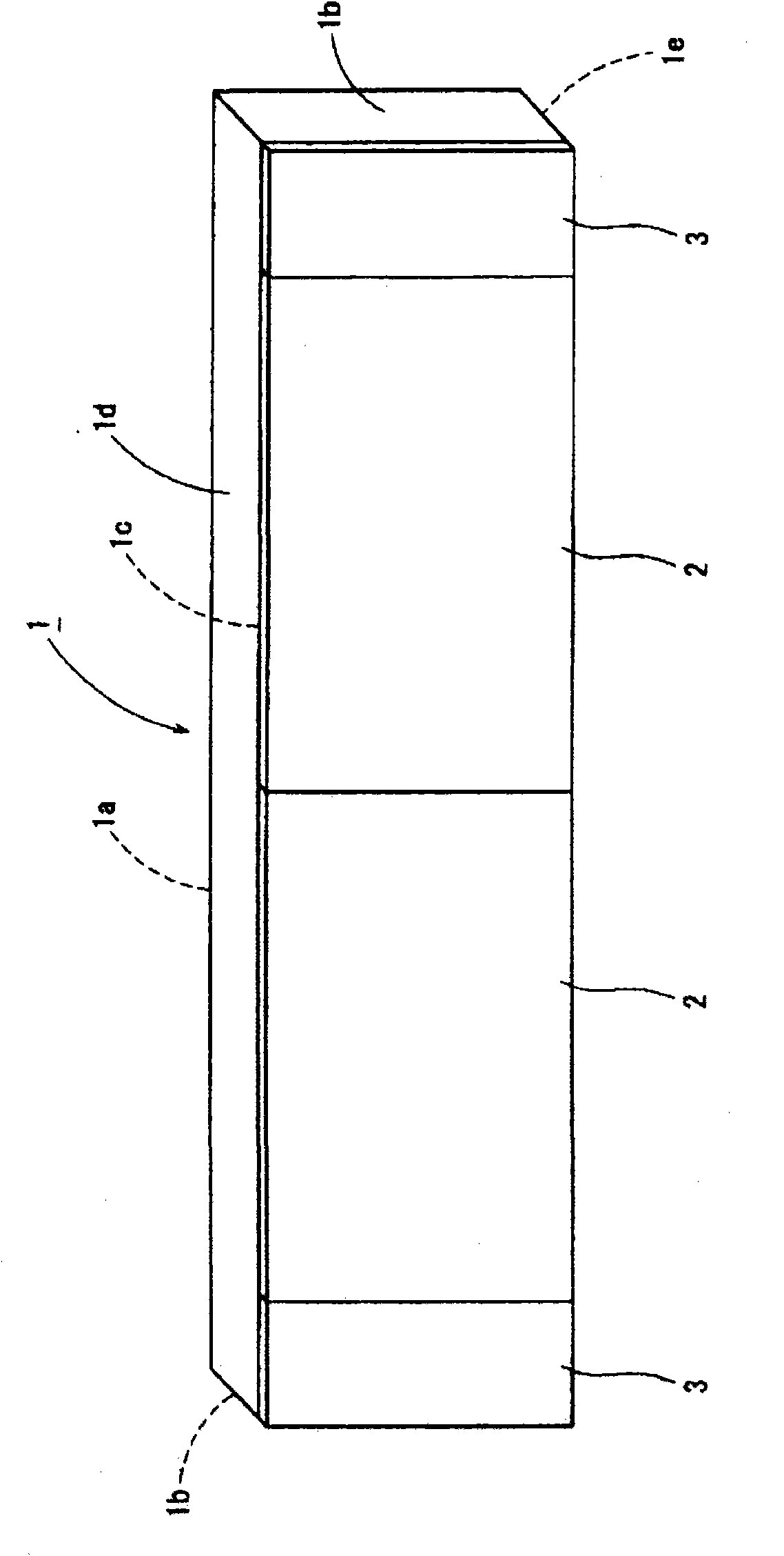
[0051] refer to Figure 1 to Figure 12 , the configuration of the indoor unit for an air conditioner according to the first embodiment of the present invention will be described.

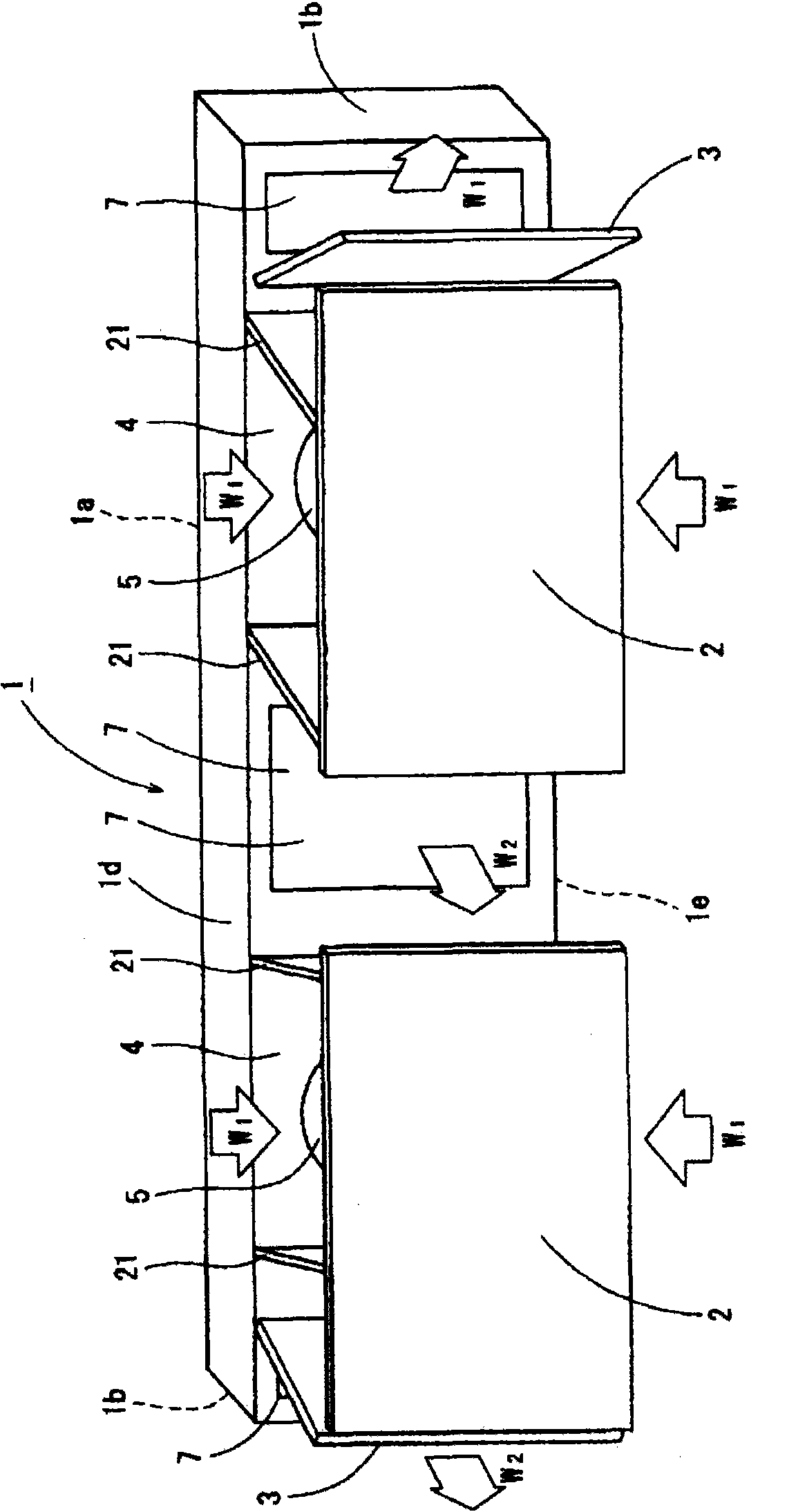
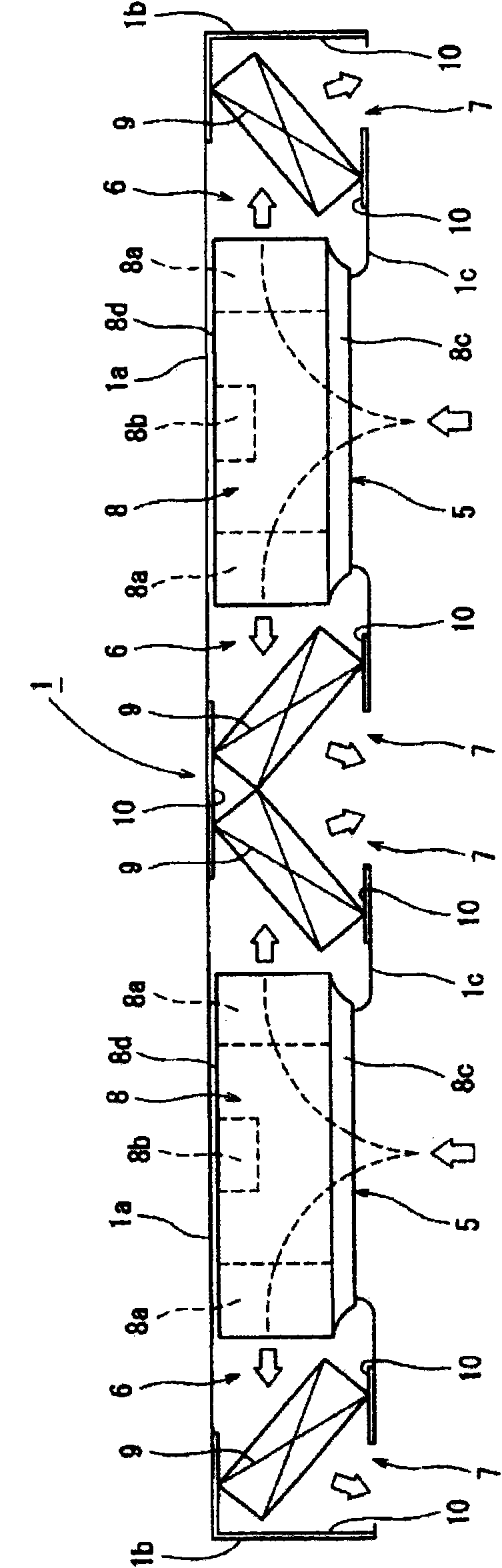
[0052] Such as Figure 1 ~ Figure 3 As shown, the indoor unit for an air conditioner is a twin type composed of a pair of indoor unit units arranged side by side. Each indoor unit is provided with a fan and two heat exchangers arranged on both sides of the fan.

[0053] The indoor unit for an air conditioner is provided with a horizontally long and thin flat box-shaped main body case 1 . The main body case 1 is composed of a rear panel (back panel) 1a, two side panels (side panels) 1b, a front panel (front panel) 1c, an upper panel (top panel) 1d, and a bottom panel (bottom panel) 1e. The back panel 1 a constitutes a mounting surface of a fan motor 8 b of a turbo fan 8 described later.

[0054]Among these panels 1a, 1b, 1c, 1d, and 1e, the panels 1b, 1c, 1d, and 1e other than the rear panel 1a a...

no. 2 approach

[0088] Next, refer to Figure 13 to Figure 16 The configuration of the indoor unit for an air conditioner according to the second embodiment of the present invention will be described.

[0089] The second embodiment differs from the first embodiment in that a step portion 15 b is formed on the drain pan 15 . Specifically, the positioning members 24 and 25 for setting the inclination angle are arranged in the drain pan 15, and the lower part of the drain pan 15 is formed with, for example, Figure 13 ~ Figure 15 The step portion 15b shown. The upper surface of the stepped portion 15b functions as a positioning member in the height direction. Step portion 15 b is formed by a wide portion at the top of drain pan 15 and a narrow portion at the bottom of drain pan 15 . On the other hand, on the outer surface of the narrow portion of the stepped portion 15b (the outer surface of the bottom of the drain pan 15), for example, Figure 16 The vacuum insulation material 10 whose thic...

no. 3 approach

[0094] Next, refer to Figure 18 ~ Figure 20 , the configuration of the indoor unit for an air conditioner according to the third embodiment of the present invention will be described.

[0095] The third embodiment is characterized in that the subcooling heat exchanger 19 having the structure of the above-mentioned first embodiment is changed from a cylindrical heat exchanger with spine fins to, for example, Figure 18 ~ Figure 20 A flat cross-fin coil subcooling heat exchanger 19 is shown.

[0096] With such a configuration, it is possible to further improve the heat exchange efficiency during supercooling.

[0097] Specifically, the cross-fin coil type subcooling heat exchanger 19 has a much thinner thickness than the above-mentioned ridge-fin type subcooling heat exchanger. Therefore, the space problem can be solved naturally, and the pressure loss of the turbofan 8 is low, and the heat exchange capacity increases by more than 50% under the same ventilation resistance val...


PUM


Abstract

An indoor unit for an air conditioner has a box-shaped body casing (1). A pair of air inlets (5) is arranged in the front face of the body casing (1). A pair of air outlets (7) is arranged on both sides of each air inlet (5). Inside the body casing (1) is formed a pair of air paths (6) leading from each air inlet (5) to the adjacent air outlets (7). Inside the body casing (1) are provided turbo fans (8) so as to correspond to respective air inlets (5), and on both sides of each turbo fan (8) is provided a pair of heat exchangers (9) so as to correspond to the pair of air outlets (7). Below the pair of heat exchangers (9) and the turbo fan (8) is provided a drain pan (15). In the drain pan (15) is received refrigerant piping (21a-21d) for connecting the pair of heat exchangers (9) to each other.

Description

technical field [0001] The present invention relates to an indoor unit for an air conditioner that can be thinned and compacted. Background technique [0002] A generally used conventional wall-mounted indoor unit for an air conditioner is disclosed in Patent Document 1, for example. The indoor unit is equipped with: two drain pans arranged front and rear, multiple λ (lambda) type cross-fin (cross fin) heat exchangers supported on these drain pans, and cross-flow heat exchangers arranged between these heat exchangers. fan. The wind passing through the heat exchanger is blown into the room through the vortex passage. [0003] However, in such a configuration, since the heat exchanger and the cross-flow fan are arranged side by side in the front-rear direction, there is a limit to reducing the thickness of the indoor unit. [0004] Therefore, the present applicant tried to make the indoor unit as thin as possible as shown in the indoor units of Patent Documents 2 and 3, for...

Claims


Application Information

Patent Timeline
Patent Type & Authority Applications(China)
IPC IPC(8): F24F13/22F24F13/30F24F1/0007F24F1/0063F24F1/0068
CPCF24F13/222F24F2001/0048F24F13/30F24F1/0007F24F1/0033F24F1/0014F24F1/26F24F1/32F24F1/005F24F1/0057F24F1/0068F24F1/0063
Inventor 安尾晃一芦田圭史西口宪岐
Owner DAIKIN IND LTD
Why Eureka
Try Eureka