Al technical title is built by PatSnap Al team. It summarizes the technical point description of the patent document.
A super-large ring rolling machine technology, applied in the direction of metal rolling, etc., can solve the problems of large deformation of the suspended side of each roll, high equipment capacity requirements, high manufacturing cost of forgings, etc., to achieve large rolling capacity, large weight, and easy processing high efficiency effect
Active Publication Date: 2010-09-08
CHINA ERZHONG GRP DEYANG HEAVY IND
View PDF7 Cites 19 Cited by
Summary
Abstract
Description
Claims
Application Information
AI Technical Summary
This helps you quickly interpret patents by identifying the three key elements:
Problems solved by technology
Method used
Benefits of technology
Problems solved by technology
[0006] Due to the single frame structure, the existing ring rolling machines generally have the following disadvantages: poor rigidity, large deformation of the suspended side of each roll during rolling, which is not conducive to improving the rolling capacity
However, this kind of large-scale barrel joint has extremely high requirements on equipment capacity, and the production is difficult. The existing ring rolling machine equipment and technology cannot adapt to its production.
Therefore, at present, the production of large-scale cylindrical forgings has to rely on large-scale hydraulic presses for free forging. This process has low production efficiency, poor dimensional accuracy, low utilization rate of forgings, multiple heating, high energy consumption, and high manufacturing costs of forgings.
Method used
Image
Click on the blue label to locate the original text in one second.
Reading with bidirectional positioning of images and text.
Examples
Embodiment
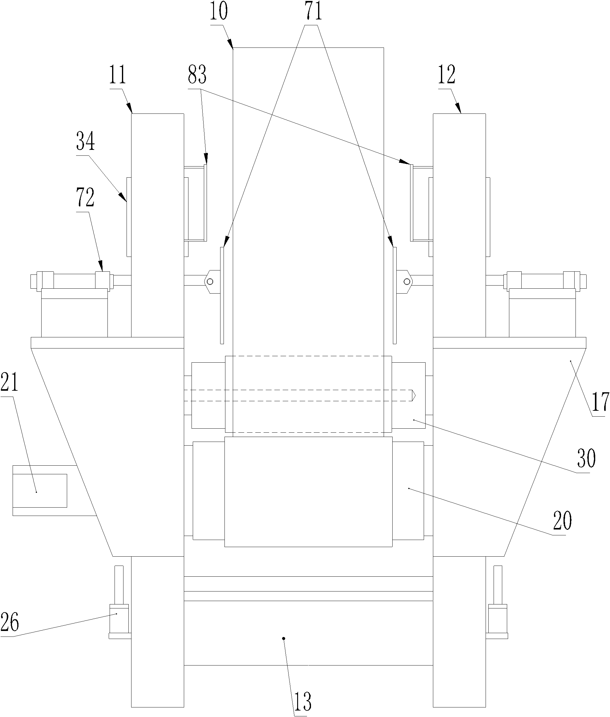
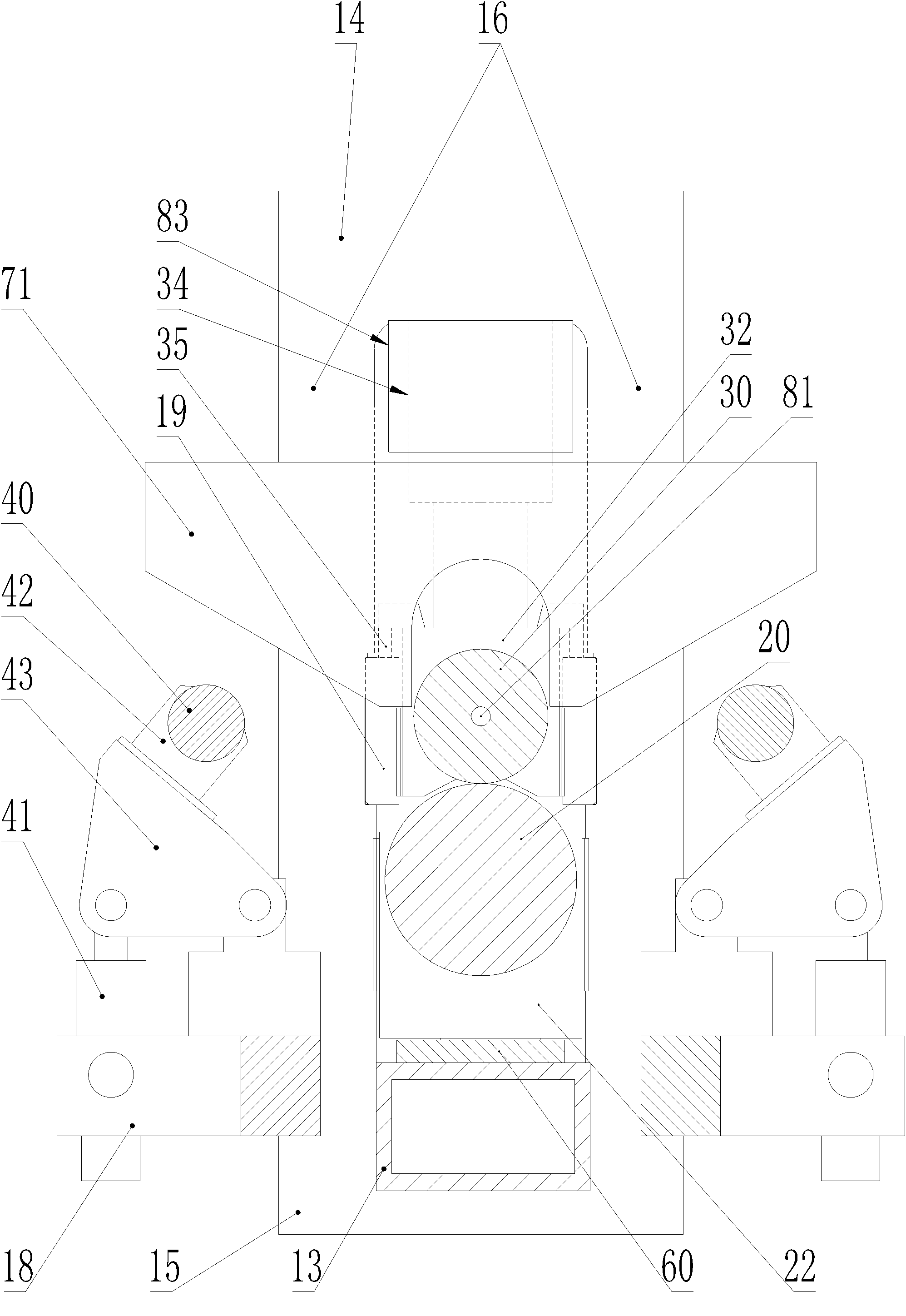
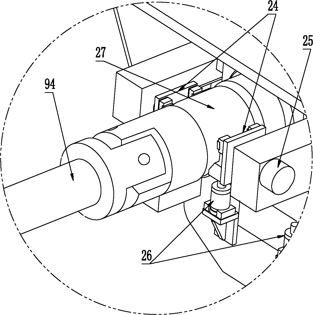
[0059] Such as figure 1 , figure 2 , image 3 , Figure 4 , Figure 5 , Figure 6 , Figure 7 , Figure 8 , Figure 9 , Figure 10 As shown, the super large ring rolling machine has a design rolling force of 5000-7000 tons, a maximum ring diameter of 8000-9000mm, and a maximum ring height of 3000-3800mm. Frame is the open frame that is formed by the bottom beam 13 between the drive side frame 11 and the operation side frame 12 that are arranged vertically and oppositely, and the bottom beam 13 between the drive side frame 11 and the operation side frame 12 bottoms. Both the drive side frame 11 and the operation side frame 12 are archway-type integrally enclosed casting frames composed of top beams 14, bottom beams 15, and upright columns 16 on both sides, and are surrounded by top beams 14, bottom beams 15, and upright columns 16. Forming the frame window, the strengthening support on the outside of the transmission side frame 11 and the operation side frame 12 is co...
PUM
Abstract
The invention relates to the field of metal pressure moulding and provides an overlarge type ring rolling machine which has large rolling force, good rigidity, high processing precision, high processing efficiency and low processing cost and can be suitable for the manufacturing requirement on a large cylindrical section. A stand of the overlarge type ring rolling machine comprises a drive side stand and an operating side stand which are longitudinally and oppositely arranged, both ends of each roll are supported, and axes are horizontally arranged; a drive roll is arranged at the lower part of the stand, and a core roll is positioned on the drive roll; at least one of double axial directions of the core roll is set to be a drawing direction of the core roll, one end of the core roll points to the other end along the drawing direction, the starting point end is a suspending end, and the terminal point end is a drawing end; a drawing unit comprises the core roll and a drawing end core roll bearing seat thereof or the core roll and core roll bearing seats at both ends of the core roll; the overlarge type ring rolling machine is provided with a roll drawing mechanism for doing reciprocating motion along the drawing direction of the core roll; and the roll drawing mechanism is provided with a detachable type fixing structure of the drawing unit. The invention is suitable for producing a large cylindrical section with large axial size, weight and wall thickness in the fields of large nuclear power, petrochemical container, aerospace, and the like.
Description
technical field [0001] The invention relates to the field of metal pressure forming, in particular to a super-large ring rolling machine for processing cylindrical forgings. Background technique [0002] Ring parts are all kinds of seamless ring forgings such as bearing rings, ring gears, flanges, hubs, etc. Ring products are widely used in machinery, automobiles, trains, ships, petrochemicals, aerospace, atomic energy, wind power and many other industrial fields . Ring rolling is also known as ring rolling, ring rolling expansion, hole expansion, and ring rolling, that is, through rolling equipment, the ring is continuously and locally plastically deformed, thereby realizing plastic processing such as wall thickness reduction, diameter expansion, and cross-sectional profile forming. craft. [0003] The commonly used equipment for ring rolling is ring rolling machine, also known as ring rolling machine, ring rolling machine, hole reaming machine, which includes frame, driv...
Claims
Application Information
Patent Timeline
Application Date:The date an application was filed.
Publication Date:The date a patent or application was officially published.
First Publication Date:The earliest publication date of a patent with the same application number.
Issue Date:Publication date of the patent grant document.
PCT Entry Date:The Entry date of PCT National Phase.
Estimated Expiry Date:The statutory expiry date of a patent right according to the Patent Law, and it is the longest term of protection that the patent right can achieve without the termination of the patent right due to other reasons(Term extension factor has been taken into account ).
Invalid Date:Actual expiry date is based on effective date or publication date of legal transaction data of invalid patent.