Heat accumulating type anti-freeze solar heat collector system
A solar heat collector and thermal storage technology, which is applied in the field of antifreeze solar heat collector systems, can solve the problems of cracked pipelines, environmental pollution, and large initial investment in antifreeze systems, achieving wide application, reducing initial investment costs, The effect of eliminating environmental pollution problems
- Summary
- Abstract
- Description
- Claims
- Application Information
AI Technical Summary
Problems solved by technology
Method used
Image

Examples
specific Embodiment approach 1
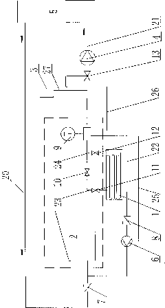
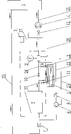
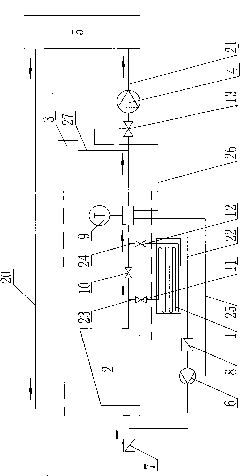
[0007] Specific implementation mode one: combine Figure 1-Figure 4 Describe this embodiment, the thermal storage type antifreeze solar heat collector system of this embodiment includes solar heat collector 2, first circulating water pump 4, heat user 5, first check valve 7, fourth stop valve 13, circulation worker The fluid outflow pipe 20 and the circulating working fluid inflowing pipe 21, the outflow end of the heat user 5 communicates with the solar heat collector 2 through the circulating working fluid outflow pipe 20, the first check valve 7 is installed on the circulating working medium outflow pipe 20, and the heat The inflow end of the user 5 communicates with the solar heat collector 2 through the circulating working medium inflow pipe 21, and the fourth shut-off valve 13 and the first circulating water pump 4 are sequentially installed on the circulating working medium inflow pipe 21 along the flowing direction of the circulating working medium. The antifreeze sola...
specific Embodiment approach 2
[0008] Specific implementation mode two: combination Figure 1-Figure 4 Illustrate this embodiment, the antifreeze solar heat collector system of this embodiment is also increased with expansion water tank 3 and the 3rd communication pipe 27, described expansion water tank 3 communicates with circulating working fluid inflow pipe 21 through the 3rd communication pipe 27, and the The three-communication pipe 27 is located on the circulating working fluid inflow pipe 21 between the temperature sensor 9 and the fourth cut-off valve 13 . Such setting plays the role of constant pressure supply. Other compositions and connections are the same as in the first embodiment.
[0009] Thermal storage mode of the present invention (see figure 2 ): the first shut-off valve 10 is closed, the second shut-off valve 11, the third shut-off valve 12, and the fourth shut-off valve 13 are opened; the circulating working medium flows out from the heat user 5, enters the solar heat collector 2 to ...
PUM
 Abstract
Description
Claims
Application Information
 - R&D
- Intellectual Property
- Life Sciences
- Materials
- Tech Scout
- Unparalleled Data Quality
- Higher Quality Content
- 60% Fewer Hallucinations
Browse by: Latest US Patents, China's latest patents, Technical Efficacy Thesaurus, Application Domain, Technology Topic, Popular Technical Reports.
© 2025 PatSnap. All rights reserved.Legal|Privacy policy|Modern Slavery Act Transparency Statement|Sitemap|About US| Contact US: help@patsnap.com