Rim material compression device of sintering machine trolley

A technology of a pressing device and a trolley is applied in the metallurgical field to achieve the effects of reducing costs, reducing air leakage rate, and facilitating installation and maintenance.

Active Publication Date: 2010-09-08
JIANGSU SHAGANG GROUP HUAIGANG SPECIAL STEEL CO LTD
View PDF5 Cites 8 Cited by
  • Summary
  • Abstract
  • Description
  • Claims
  • Application Information

AI Technical Summary

Problems solved by technology

[0010] The purpose of the present invention is to design a sintering machine trolley edge material pressing device to overcome the relatively serious edge effect existing in the production process

Method used


Image

  • Rim material compression device of sintering machine trolley
  • Rim material compression device of sintering machine trolley
  • Rim material compression device of sintering machine trolley

Examples


Embodiment Construction

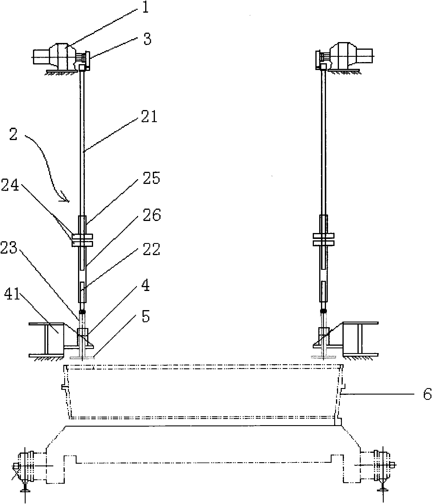
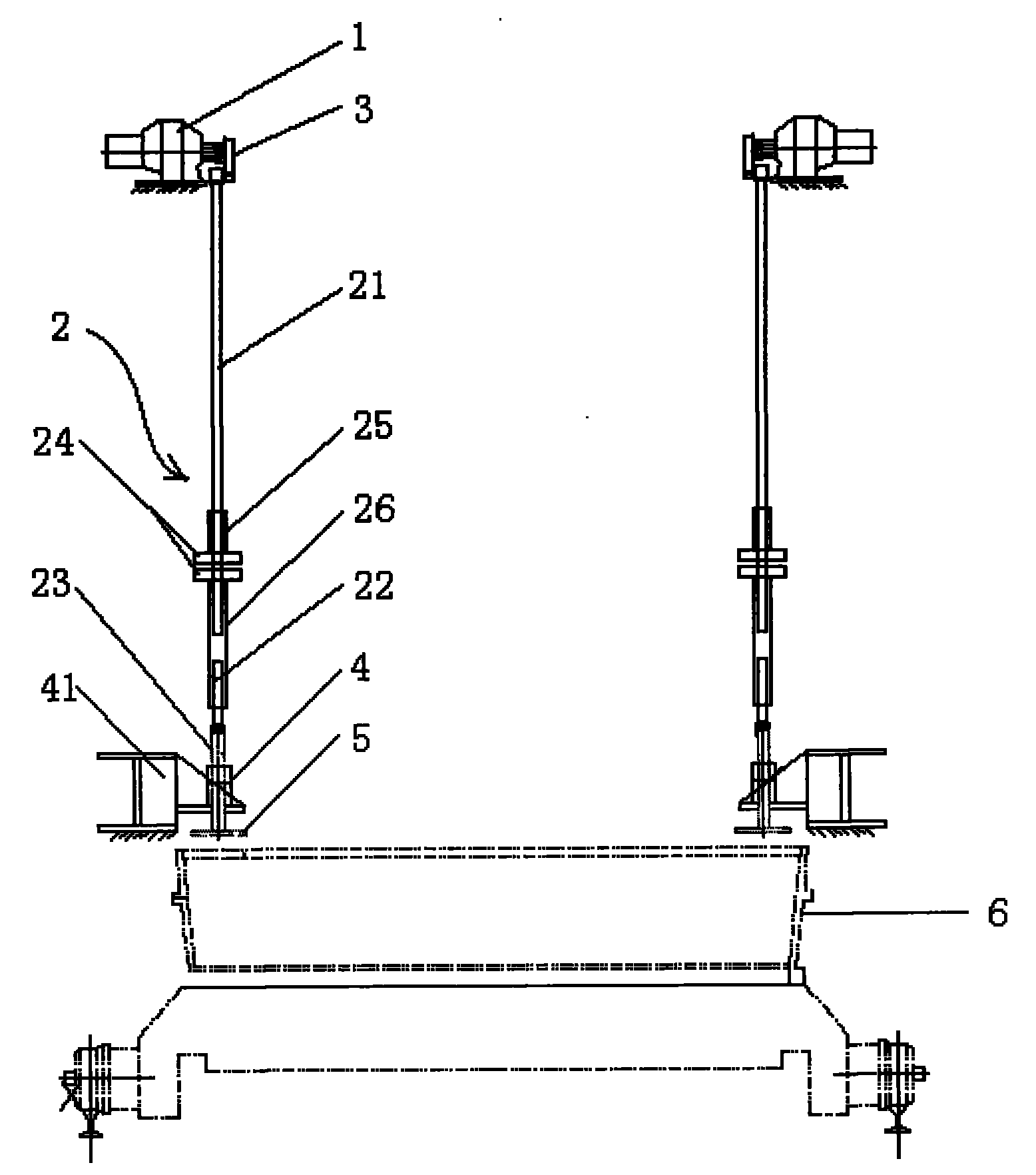
[0029] Such as figure 1 As shown, a sintering machine trolley edge material pressing device includes a power unit 1 (in this embodiment, the power unit adopts a reducer) and a pressing rod 2 . The output shaft of the power device 1 is provided with an eccentric wheel 3 , and the pressing rod 2 includes a first pressing rod 21 , a second pressing rod 22 , and a sliding guide rod 23 . The upper end of the first pressing rod 21 is provided with a bearing seat, and its shaft is fixedly connected to the distal end of the eccentric wheel 1 .

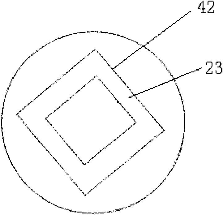
[0030] still as figure 1 As shown, the lower end of the first compression rod 21 and the connecting end of the second compression rod 22 are provided with a height adjustment device, and the lower end of the second compression rod 22 is connected to the sliding guide rod 23 through a bearing, and the lower end of the sliding guide rod 23 passes through The guide device 4 is provided with a pressure plate 5 .

[0031] The height adjustment d...


PUM


Abstract

The invention discloses a rim material compression device of a sintering machine trolley, which comprises a motive power device and a compression rod, wherein an eccentric wheel is arranged on an output shaft of the motive power device, the upper end of the compression rod is connected with the eccentric wheel through a bearing, and the lower end of the compression rod passes through a guide device and is provided with a material pressure plate. A material pressing device of the invention is not needed to be stopped when the material pressing pressure is regulated, and the material pressing depth can be regulated at proper time through directly rotating a lower pattern disc with a pressing rod provided a second connecting sleeve, so the optimal sintering effect can be reached. Because of the implementation of the invention, wind rate becomes uniform and consistent in the width direction of the sintering machine trolley, the rim effect is effectively controlled, the effective air rate can be fully utilized, the yield and the quality of the sintering ore can be improved, and the cost of the sintering ore can be reduced.

Description

technical field [0001] The invention belongs to the field of metallurgy, and in particular relates to a control device for the thickness of side material on both sides of a sintering machine trolley in a steel plant. Background technique [0002] With the development of my country's iron and steel industry, natural rich iron ore is far from meeting the needs of blast furnace smelting in terms of output and quality, while a large number of lean ore concentrates and natural rich ore powders obtained after beneficiation cannot be directly imported Blast furnace smelting. In order to solve this contradiction, people use artificial methods to make these fine ore into massive man-made rich ore for use in blast furnaces. This not only opens up a new way for us to use lean iron ore resources, but also solves the problem of insufficient natural rich ore. It can also develop new high-quality raw materials for the further development of my country's iron and steel industry by improving ...

Claims


Application Information

Patent Timeline
IPC IPC(8): F27B21/08
Inventor 翁玉明周四君刘海洋谢春阳董培军徐鸣
Owner JIANGSU SHAGANG GROUP HUAIGANG SPECIAL STEEL CO LTD
Why Eureka
Try Eureka