Image motion compensation method for space optical remote sensor

A space optical remote sensing and image motion compensation technology, applied in the field of image motion compensation, can solve the problems of inability to meet the needs of complex imaging tasks, inaccurate calculation results, etc., and achieve the effect of simple derivation process, single application situation, and high calculation accuracy.

Inactive Publication Date: 2010-09-08
HARBIN INST OF TECH
View PDF0 Cites 41 Cited by
  • Summary
  • Abstract
  • Description
  • Claims
  • Application Information

AI Technical Summary

Problems solved by technology

[0006] The purpose of the present invention is to solve the problems existing in the current calculation method of the image motion velocity vector used for image motion compensation that cannot meet the needs of complex imaging tasks and the calculation results are inaccurate, and provides an image motion compensation method for space optical remote sensing sensors

Method used


Image

  • Image motion compensation method for space optical remote sensor
  • Image motion compensation method for space optical remote sensor
  • Image motion compensation method for space optical remote sensor

Examples


specific Embodiment approach 1

[0016] Specific embodiment one: the image motion compensation method of the space optical remote sensing sensor of the present embodiment, its process is as follows:

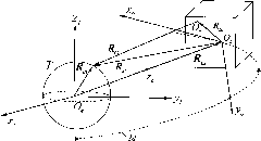
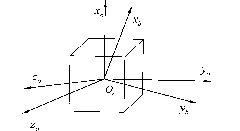
[0017] Step 1. Let T represent the ground target, i represent the image of the ground target T formed by the space optical remote sensing sensor, then according to the position and vector relationship between the image i and the ground target T, establish a description from the ground target T to the image i Five Cartesian coordinate systems, the five Cartesian coordinate systems are: geocentric equatorial coordinate system, satellite orbit coordinate system, satellite body coordinate system, camera coordinate system and image plane coordinate system;

[0018] Step 2, carry out coordinate transformation to the five Cartesian coordinate systems established in step 1, and obtain the formula for calculating the T position of the ground target in the camera coordinate system;

[0019] Step 3. According to the formul...


PUM


Abstract

The present invention provides an image motion compensation method for a space optical remote sensor, relating to an image motion compensation method and solving the problem that the current image motion velocity vector calculation method used in image motion compensation cannot satisfy complex imaging tasks and the calculation result is not accurate. The process of the image motion compensation method is as follows: creating five coordinate systems starting from ground targets to image points, transferring the coordinates for a plurality of times according to the rotation and translation principles among vectors, describing the positions of the targets and the image points in the camera coordinate systems, obtaining the image motion velocity vector calculation formula and the calculation method when the satellite forms images of the targets, then obtaining the image motion velocity vector used in the image motion compensation of the space optical remote sensor. The image motion compensation method overcomes the deficiency in the prior art, dependently calculates the target positions needed in the image motion velocity vector calculation and integrally considers the orbit and attitude parameters, besides. The image motion compensation method is suitable for complex imaging tasks and general satellite orbit, and is used in the fields such as atmospheric environment monitoring, resources exploration, disaster prevention and the like.

Description

technical field [0001] The invention relates to an image motion compensation method. Background technique [0002] The space optical remote sensing camera has the characteristics of large observation range, fast observation speed, monitoring and reconnaissance, and has become one of the main payloads of military and scientific research satellites. The TDI (Time Delay and Integration)-CCD (Charge CouTled Device) linear array push-broom camera is used as the optical remote sensing sensor. The weaker signal obtained can be superimposed into a stronger signal output, so as to obtain sufficient photoelectric sensitivity and signal-to-noise ratio. During the in-orbit imaging of satellites, due to reasons such as the rotation of the earth itself and the stability of the satellite platform, the motion direction of the line array is different from the actual imaging direction of the camera. Velocity is the image motion velocity. In order to ensure clear imaging of the target, the ...

Claims


Application Information

Patent Timeline
Patent Type & Authority Applications(China)
IPC IPC(8): G01C25/00G01C11/02
Inventor 孙兆伟仲惟超邓泓梁海朝王剑颖吴限德
Owner HARBIN INST OF TECH
Why Eureka
Try Eureka