Unlock instant, AI-driven research and patent intelligence for your innovation.

Offset capacitance automatic calibration circuit and method

A technology of automatic calibration and offset capacitance, which is applied in the direction of measuring electrical variables, instruments, measuring devices, etc., can solve the problems of increasing circuit complexity and cost, not easy to use, increasing the complexity of the circuit system, etc., to achieve low circuit implementation complexity, Quantity reduction, manual adjustments for accurate results

Active Publication Date: 2010-09-08
PEKING UNIV
View PDF5 Cites 11 Cited by
  • Summary
  • Abstract
  • Description
  • Claims
  • Application Information

AI Technical Summary

Problems solved by technology

The compensation accuracy of the external compensation voltage method is determined by the accuracy of the applied voltage amplitude, and peripheral circuits are required to generate an adjustable amplitude compensation voltage, which increases the complexity of the circuit system; the on-chip compensation capacitor array method needs to achieve high precision and a wide range of offset capacitors Compensation requires a larger capacitor array and more control signals and interfaces, which also increases the complexity and cost of the circuit; due to the limitation of the process, the differential offset capacitance of each sensor is also different, so the traditional manual adjustment The offset capacitance compensation method requires manual testing and calibration for each sensor, which is not easy to use

Method used


Image

  • Offset capacitance automatic calibration circuit and method
  • Offset capacitance automatic calibration circuit and method
  • Offset capacitance automatic calibration circuit and method

Examples


Embodiment

[0037] This embodiment first specifically describes the structural features of the offset capacitor automatic calibration circuit provided by the technical solution of the present invention.

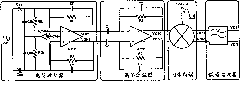
[0038] like figure 2 As shown, the circuit includes three parts: a normal readout circuit, a capacitance automatic compensation circuit and a control signal generation circuit.

[0039] Wherein, the normal readout circuit includes a charge amplifier 201 and a follow-up readout circuit 202; C1 and C2 are the detection capacitors of the sensor, that is, capacitors that need to be matched, and one of their ends is connected to vac, and the other end is connected to the charge amplifier 201 respectively. The two input terminals of the charge amplifier 201 are connected to the two input terminals of the subsequent readout circuit 202.

[0040] The control signal generation circuit is mainly an oscillator 203, wherein the output terminal vac of the oscillator 203 is connected to the compensa...


PUM


Abstract

The invention relates to an offset capacitance automatic calibration circuit in an MEMS sensor capacitance read-out circuit and a method, which belong to the technical field of microelectronic integrated circuit design and microelectronic MEMS. Through aiming at the problems in the prior art, the invention provides the offset capacitance automatic calibration circuit and the method. The circuit comprises a reset circuit, a comparison circuit, a successive approximation circuit and a compensation capacitance array circuit, wherein the reset circuit is used for carrying out reset and replacement on a charge amplifier, the comparison circuit is used for reading and comparing output signals of the charge amplifier, the successive approximation circuit is used for receiving comparison results and generating capacitance compensation control codes, and the compensation capacitance array circuit is used for forming compensation capacitance on the sensor capacitance according to the instructions of the capacitance compensation control codes. The technical scheme only needs a calibration starting signal, the circuits can automatically regulate the size of the compensation capacitance to realize the capacitance compensation after N+1 carrier wave periods, the invention has the advantages of convenience, high speed and easy use, and the accuracy is higher than that of the manual regulation. The circuit realization complicity is low, in addition, the circuit power consumption is greatly reduced, and the invention has high practical application value.

Description

technical field [0001] The invention belongs to the field of microelectronic integrated circuit design and microelectronic MEMS technology, and relates to a capacitive sensor detection and capacitance detection technology in a control circuit, in particular to an automatic calibration circuit and method for an offset capacitance in a capacitance readout circuit of a MEMS sensor. Background technique [0002] Capacitive MEMS (Micro-Electro-Mechanical Systems, micro-mechanical systems) has broad application prospects in military, industrial control, automotive and consumer electronics and other fields, such as capacitive MEMS gyroscopes, capacitive MEMS accelerometers, etc. Very small capacitance, usually in the range of 10 -2 -10 -15 The farad-level detection circuit is one of the key components of the capacitive MEMS sensor system. This part is composed of the sensor differential detection capacitance and the C / V (Capacitance to Voltage, capacitance-voltage) conversion circ...

Claims


Application Information

Patent Timeline
IPC IPC(8): G01R35/00
Inventor 方然鲁文高陈中建张雅聪鞠原刘仁直郭娟肖永强吉利久
Owner PEKING UNIV