Supercharge Your Innovation With Domain-Expert AI Agents!

Vision inspection apparatus

A visual inspection and instrument technology, applied in the field of visual inspection instruments, can solve problems such as the inability to perform visual inspection smoothly, reduce the reliability of visual inspection, and fail to measure accurate images, so as to achieve smooth visual inspection, increase productivity, and enhance reliability. Effect

Inactive Publication Date: 2012-10-10
JT
View PDF5 Cites 0 Cited by
  • Summary
  • Abstract
  • Description
  • Claims
  • Application Information

AI Technical Summary

Problems solved by technology

This can change the position of the electronic component, causing errors in measuring the precise position of the electronic component, or making it impossible to measure an accurate image of the electronic component
As a result, the reliability of vision inspection may be reduced or vision inspection may not be performed smoothly

Method used


Image

  • Vision inspection apparatus
  • Vision inspection apparatus
  • Vision inspection apparatus

Examples


Embodiment Construction

[0050] Hereinafter, the present invention will be described in detail with reference to the accompanying drawings.

[0051] Next, the vision inspection apparatus according to the present invention will be explained in detail with reference to the accompanying drawings.

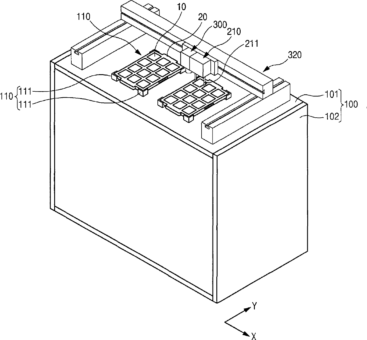
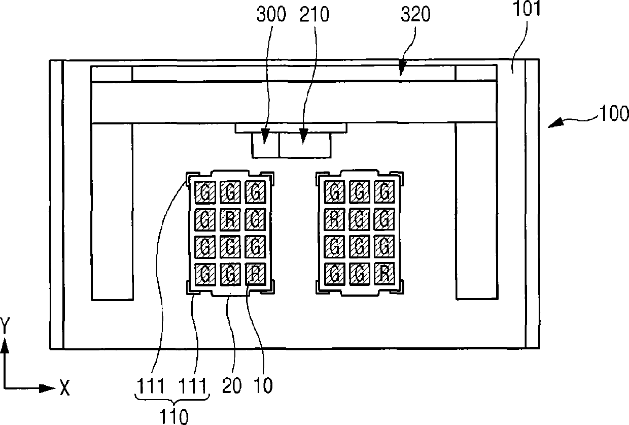
[0052] figure 2 is a perspective view of the visual inspection instrument according to the first embodiment of the present invention, and Figures 3A-3C for showing figure 2 A plan view of the operation of the visual inspection instrument in .

[0053] Such as figure 2 As shown in , the visual inspection instrument according to the first embodiment of the present invention includes: a body 100; two or more trays 20 mounted on a tray installation unit 110 and loaded with electronic components 10 thereon for visual inspection, The tray installation unit 110 is fixedly installed in the body 100; the visual inspection unit 300 is used to visually inspect the electronic components 10 loaded in the tray 20; a...


PUM


Abstract

Disclosed is a vision inspection apparatus, especially disclosed is a vision inspection apparatus capable of inspecting the appearance of an electronic element stacked on a tray. The vision inspection apparatus comprises two or more trays loading with electronic elements thereon; a vision inspection unit for performing the vision inspection to the electronic elements loaded in the trays; and a toppling unit for enabling the quality products and the inferior products to be interchanged mutually between trays, wherein, good quality electronic elements are placed in one or more trays by the toppling unit, and the inferior electronic elements are placed in the rest one or more trays.

Description

technical field [0001] The invention relates to a visual inspection instrument, in particular to a visual inspection instrument capable of detecting the appearance of electronic components loaded in a tray. Background technique [0002] Electronic components such as semiconductor packages are subjected to various inspections such as electrical tests and external tests during manufacture or before being put into the market in order to improve yield and enhance product reliability. [0003] For example, semiconductor packages are fabricated through a variety of processes, including on-wafer fabrication, dicing, and packaging. If subsequent processes are also unnecessarily performed on inferior semiconductor devices, it may increase the overall manufacturing cost. In order to prevent this problem, the above-mentioned tests are carried out before the main process, thereby screening out high-quality electronic components. Then, these selected high-quality electronic components ...

Claims


Application Information

Patent Timeline
Patent Type & Authority Patents(China)
IPC IPC(8): H01L21/66
CPCG01N21/01G01N21/8851G01N21/89H01L21/67271H01L21/67288
Inventor 柳弘俊尹芸重
Owner JT
Features
  • R&D
  • Intellectual Property
  • Life Sciences
  • Materials
  • Tech Scout
  • Unparalleled Data Quality
  • Higher Quality Content
  • 60% Fewer Hallucinations
Learn More