
Underwater aeration device

A technology for aeration devices, air, applied in the direction of pump devices, mixers with rotary stirring devices, components of pumping devices for elastic fluids, etc., to achieve improved suction and discharge, prevent clogging, improve aeration effect of action

Active Publication Date: 2012-10-03
TSURUMI SEISAKUJO
View PDF2 Cites 0 Cited by
  • Summary
  • Abstract
  • Description
  • Claims
  • Application Information

AI Technical Summary

Problems solved by technology

Since it is desirable to remove large solid materials that have entered the waste water by means of a screen device arranged upstream of the liquid storage tank, conventional submerged aerators are not provided with the ability to remove inclusions that cannot thus be removed by means of a screen device. Objects (hereinafter referred to as "foreign objects") function of the filter or similar components

Method used


Image

  • Underwater aeration device
  • Underwater aeration device
  • Underwater aeration device

Examples


Embodiment 1

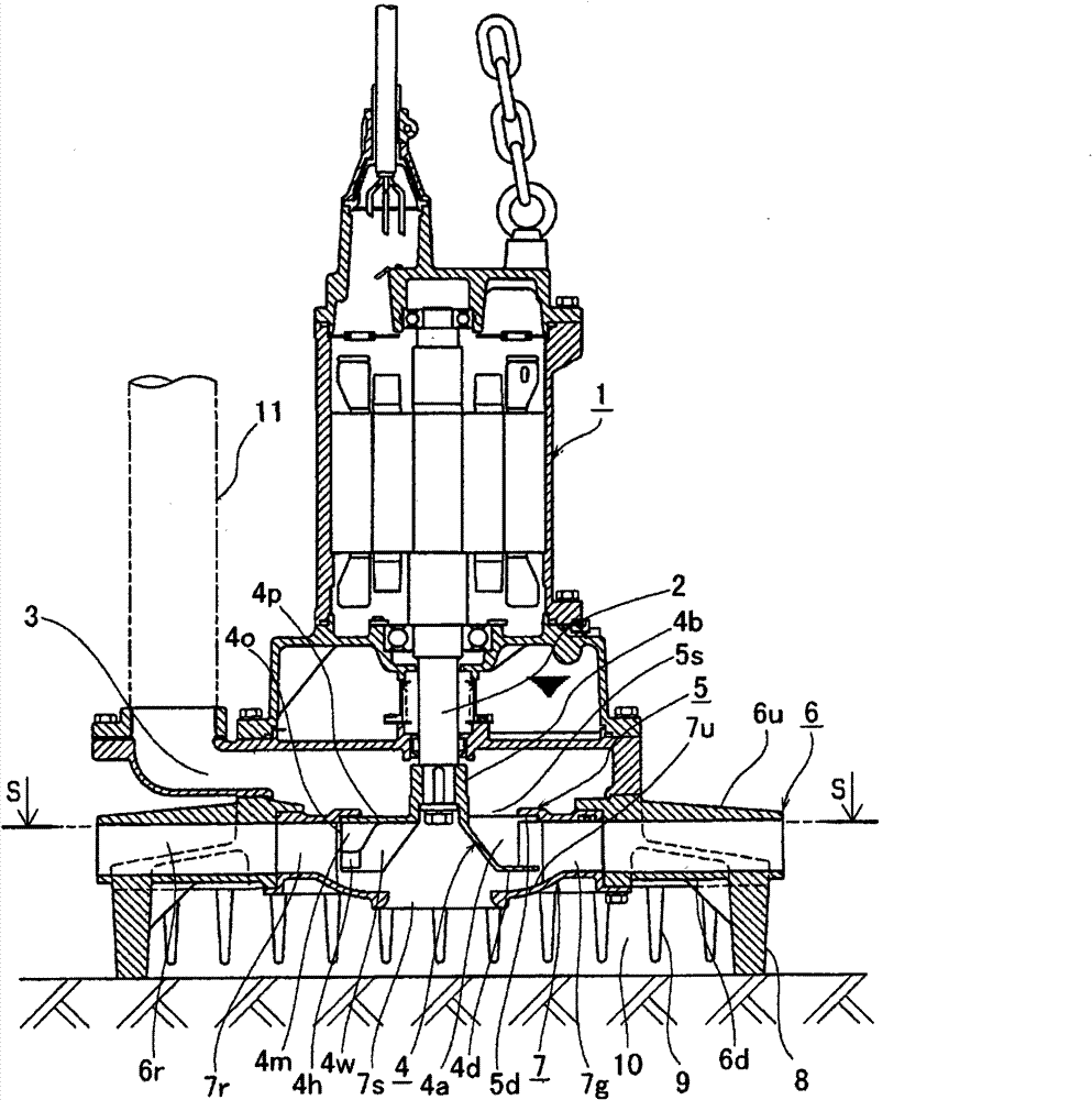
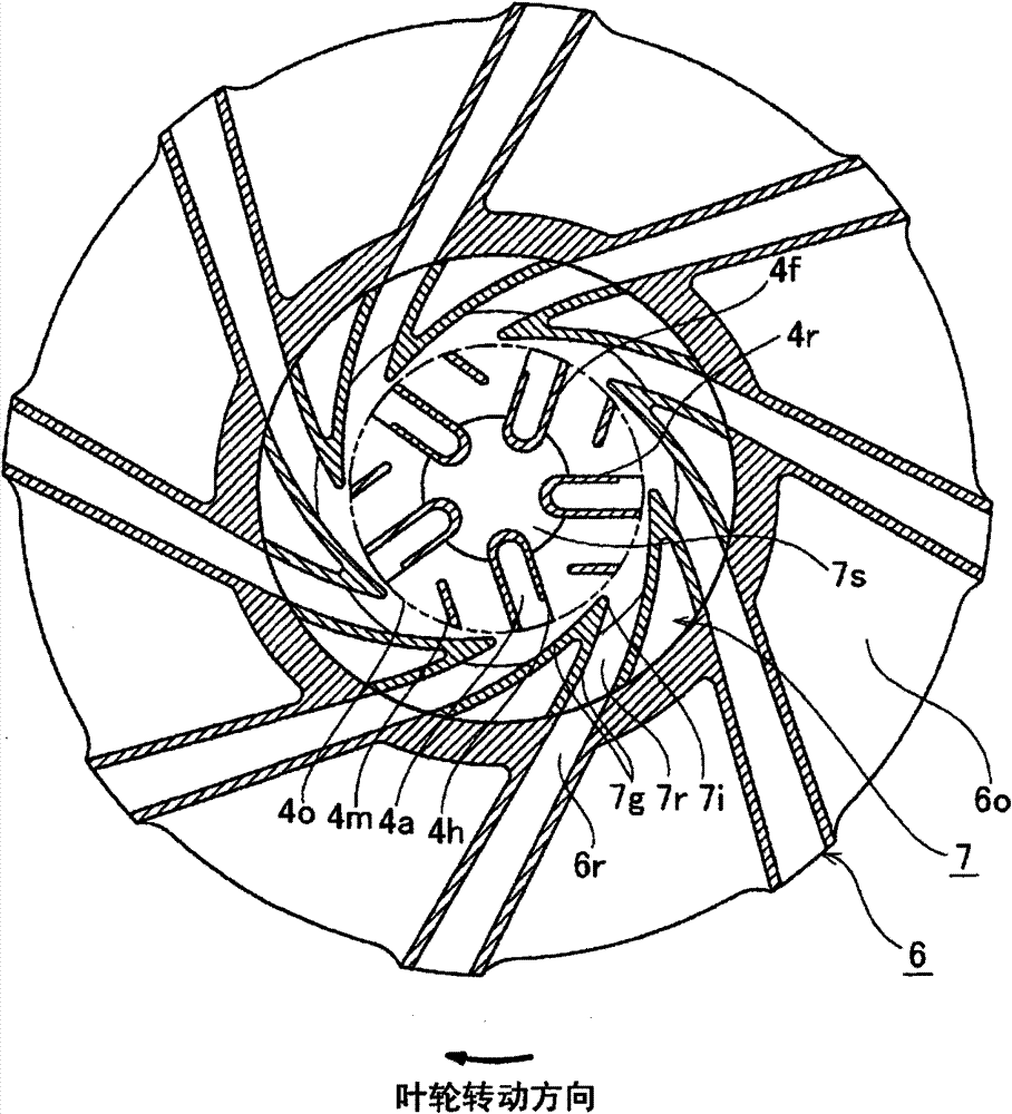
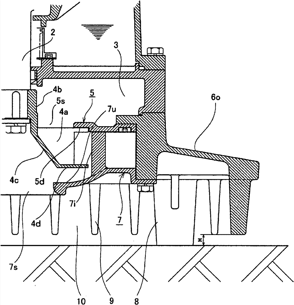
[0027] exist Figures 1 to 3 In , reference numeral 1 denotes a motor driving the submerged aeration device; and reference numeral 2 denotes a motor shaft extending downward from motor 1 and penetrating into air chamber 3 . A hub portion 4 b of the impeller 4 is fitted onto the end of the motor shaft 2 . The impeller 4 includes a circular main plate 4p extending radially outward from a hub portion 4b. The intermediate plate 5 having the air suction opening 5s at its center is attached to the top wall 6u of the guide case 6 so that the intermediate plate 5 faces the upper surface of the peripheral portion of the main plate 4p. A suction cover 7 having a liquid suction opening 7s at its center is attached to the bottom wall 6d of the guide case 6 so that the suction cover 7 faces the lower end surface 4d of the blade 4c of the impeller 4 . A plurality of guide vanes 7g are provided on the upper surface 7u of the suction cover 7 so that a gap is left between the guide vanes 7g ...


PUM


Abstract

To provide an underwater aeration device enabling prevention of closure with foreign matter, performing enhanced aeration, started under a lightened load, operated with a lessened maintenance work at a lower running cost, and manufactured at a lower cost. [MEANS FOR SOLVING PROBLEMS] An impeller (4) having a partition for sectioning a liquid passage (4w) and an air passage (4a) formed on a blade (4c) is interposed rotatably between the lower surface (5d) of an intermediate plate in which an air inlet (5s) is made and the upper surface (7u) of a suction cover in which a liquid inlet (7s) is made and contained in a guide casing (6). The liquid passage (4w) and the air passage (4a) at the distal end of the outer circumference of the partition on the back (4r) side of the blade are made to communicate with each other (4h). An intermediate impeller (4m) is provided on the outer circumference of the liquid passage (4w). The clearance between the lower end face (4d) of the blade and the upper surface (7u) of the suction cover is formed into a cone shape which is wide at the liquid inlet (7s) and narrow at the outer circumference including the guide vane tongue portion. A plurality of stand legs (8) and strainer projections (9) are projected integrally from the lower end face on the outer circumference of the lower wall (6d) of the guide casing. The upper surface (6o) of the upper wall between the air and liquid ejection passages is recessed as a down slope inclination surface widened toward the outer circumference.

Description

technical field [0001] The present invention relates to an underwater aeration device (hereinafter referred to as "submersible aeration device"), which is placed in an aeration tank for treating industrial wastewater or urban sewer wastewater. Background technique [0002] It is known to have a submerged aeration device in which, by means of the negative pressure self-suction effect of rotating the impeller in the liquid storage tank, the impeller sucks air from the atmosphere through the air duct, and sucks the waste water flowing into the storage tank (hereinafter referred to as "liquid to be treated"), mixes it with the sucked air and ejects the air-liquid mixture in the tank, thereby causing aeration. The impeller has a special structure; that is, it includes an air suction channel for sucking air and a liquid suction channel for sucking liquid to be treated. Since it is desirable to remove large solid materials that have entered the waste water by means of a screen dev...

Claims


Application Information

Patent Timeline
Patent Type & Authority Patents(China)
IPC IPC(8): C02F3/20B01F3/04F04D7/02
CPCC02F3/206B01F7/1635F04D29/2288F04D7/02F04D13/086B01F7/00733B01F3/04617Y02W10/10B01F23/23342B01F27/25B01F27/8111
Inventor 田中裕之松本早登士
Owner TSURUMI SEISAKUJO
Learn More