Indirect speed reducing device of transmission system of electric automobile

A transmission system and deceleration device technology, applied in control devices, vehicle components, transportation and packaging, etc., can solve problems affecting the normal operation efficiency and service life of motors, high requirements for concentric butt joint accuracy, increased friction and noise, etc. Achieve the ability to increase charging endurance, reduce the influence of conduction and magnetic field density, and increase the driving force and traction effect

Inactive Publication Date: 2010-09-15
郭义
View PDF6 Cites 2 Cited by
  • Summary
  • Abstract
  • Description
  • Claims
  • Application Information

AI Technical Summary

Problems solved by technology

However, this design will bring greater difficulty in the production process, as well as problems such as easy damage, high noise, and high energy consumption during product use.
One of the reasons is that in terms of production technology, when the drive motor is directly connected to the reducer, the concentric docking accuracy of the motor and the reducer is too high, and a slight error in the concentricity of the connection will easily increase the friction and friction during operation. Noise; second, during the use of the product, especially in the case of large traction, low motor speed, and increased torque, the concentric connection between the motor and the reducer is more likely to produce elastic deformation of the output shaft, making the product The friction and noise are continuously increased during the operation process; thirdly, this deceleration method makes the end cover of the motor directly connected with the reducer, and when the motor runs at high speed, the reducer will generate a magnetic field, which directly affects the conduction of the motor coil. Pass and interfere with the magnetic field density of the motor, and directly increase the thermal accumulation temperature of the motor, affecting the normal operation efficiency and service life of the motor

Method used


Image

  • Indirect speed reducing device of transmission system of electric automobile
  • Indirect speed reducing device of transmission system of electric automobile

Examples


Embodiment Construction

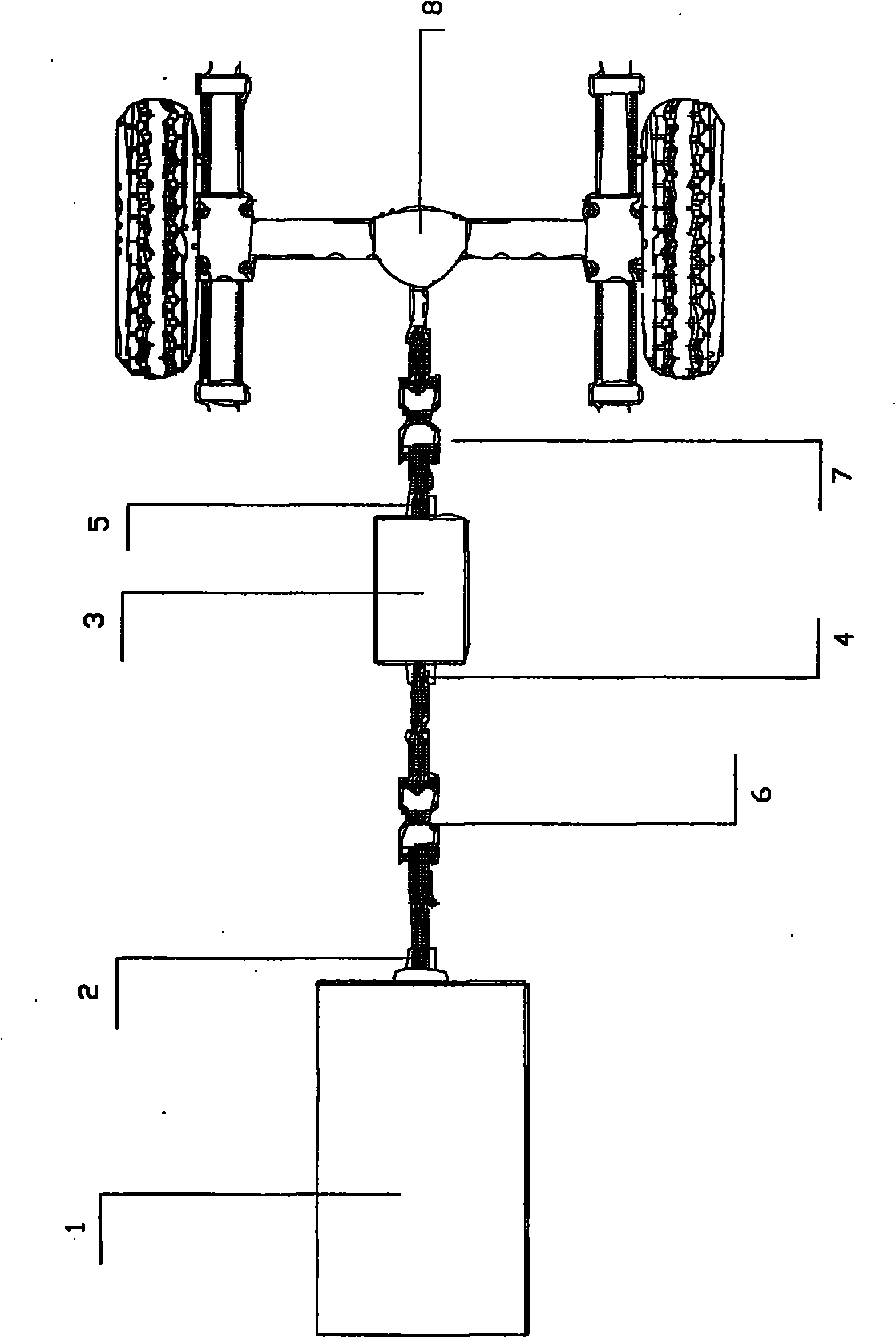
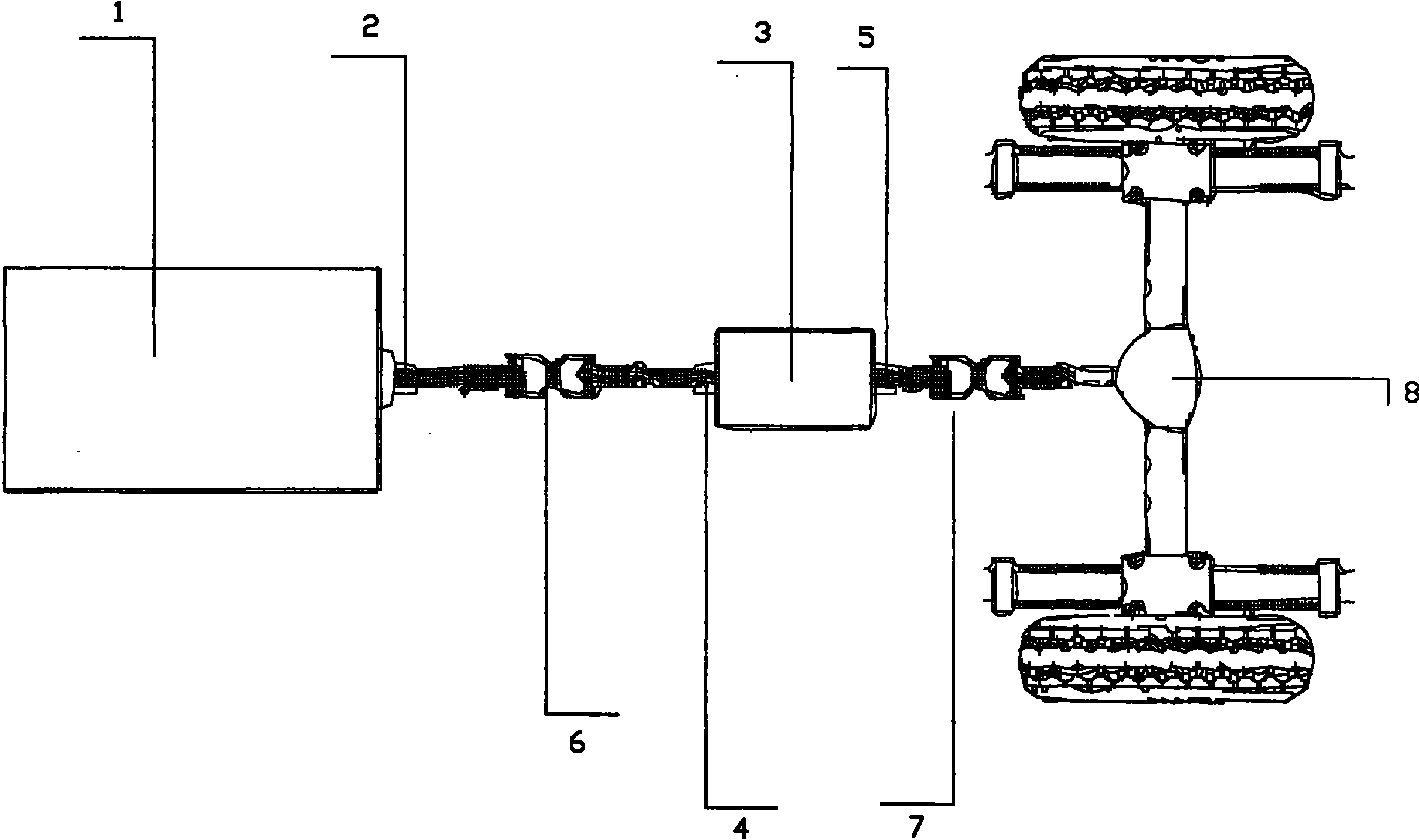
[0012] Such as figure 1 As shown: the present invention mainly includes: motor 1, motor output shaft 2, reducer 3, reducer input shaft 4, reducer output shaft 5, first universal joint 6, second universal joint 7, drive axle 8 . A first universal joint 6 is arranged between the motor 1 and the reducer 3 , so that the motor 1 and the reducer 3 are connected through the first universal joint 6 . The specific embodiment is that the output shaft 2 of the motor 1 is connected with one end of the first universal joint 6, and the input shaft 4 of the reducer is connected with the other end of the first universal joint 6; the output shaft 5 of the reducer 3 is connected with the second universal joint 6. One end of the joint 7 is connected, and the other end of the second universal joint 7 is connected with the drive axle 8 .

[0013] The above descriptions are only preferred embodiments of the present invention, and do not limit the present invention in any form. Although the presen...


PUM


Abstract

The invention discloses an indirect speed reducing device of a transmission system of an electric automobile, comprising a motor, a motor output shaft, a speed reducer, a speed reducer input shaft, a speed reducer output shaft and a drive axle. The indirect speed reducing device is characterized in that a first universal joint is connected between the motor and the speed reducer, and the other end of the speed reducer is connected with the drive axle through a second universal joint. The invention has the characteristic that since the universal joint is arranged between the motor and the speed reducer, the direct connection (hard connection) between the motor and the speed reducer is changed into indirect connection (soft connection), and the purpose of speed reduction is achieved.

Description

Technical field: [0001] The invention relates to an electric vehicle transmission system, in particular to an indirect speed reduction device for the electric vehicle transmission system. Background technique: [0002] In the existing technical field of electric vehicles, when it comes to the deceleration design of the transmission system, the direct connection between the drive motor and the reducer is generally adopted, and the deceleration effect is achieved by reducing the transmission speed of the output shaft. However, this design will bring greater difficulty in the production process, as well as problems such as easy damage, high noise, and high energy consumption during product use. One of the reasons is that in terms of production technology, when the drive motor is directly connected to the reducer, the concentric docking accuracy of the motor and the reducer is too high, and a slight error in the concentricity of the connection will easily increase the friction a...

Claims


Application Information

Patent Timeline
IPC IPC(8): B60K17/06
Inventor 郭义
Owner 郭义
Why Eureka
Try Eureka