

Beam spanning multilayer deck
A panel and bottom layer technology, applied in bridges, buildings, etc., can solve problems such as unfavorable full utilization, unfavorable girder height, difficulty in adapting to long-span girder bridge structures, etc., to save land resources and urban space, and improve vertical overall stability , Improve the effect of passing ability
- Summary
- Abstract
- Description
- Claims
- Application Information
AI Technical Summary
Problems solved by technology
Method used
Image

Examples
Embodiment 1
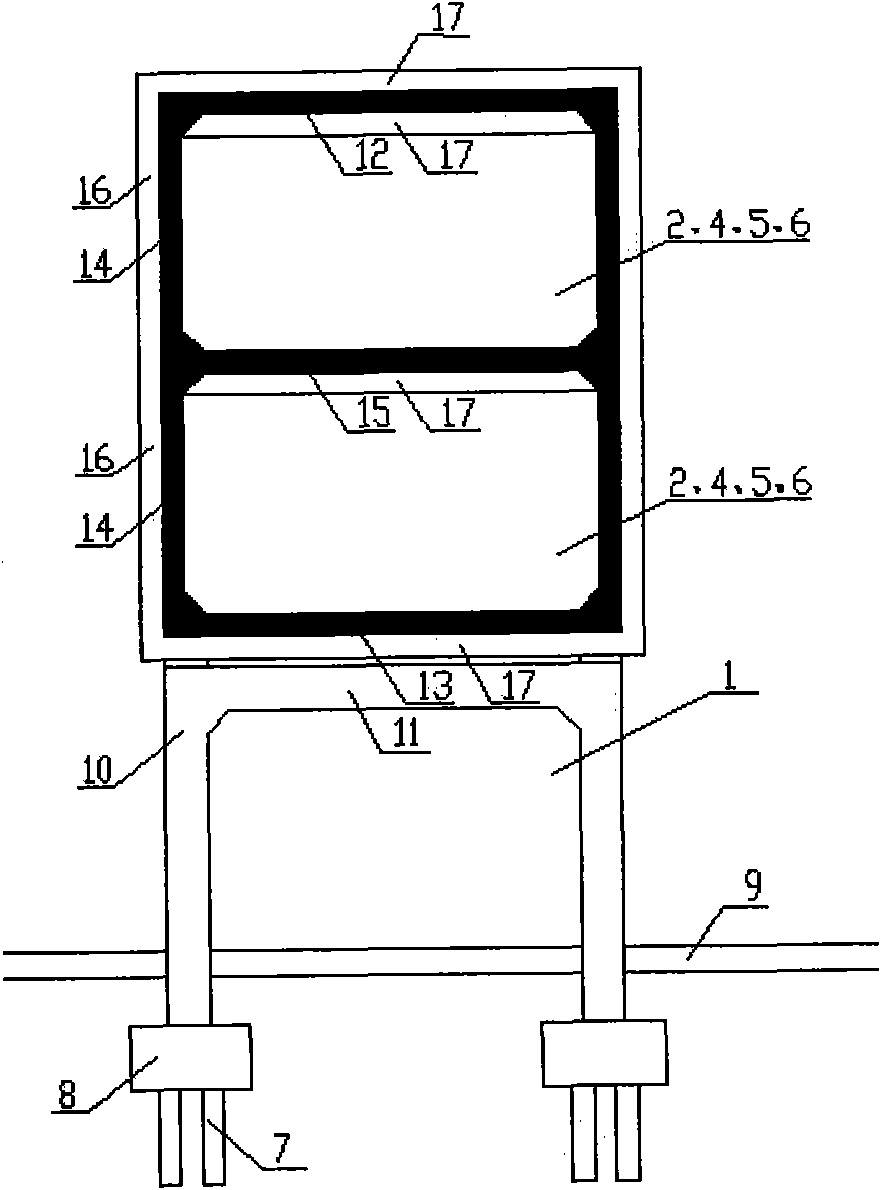
[0096] Example 1: A1-type cross-story beam with grid-shaped cross section
[0097] see figure 1 , The cross-floor beam is integrally connected by the web 14 , the upper flange 12 , the lower flange 13 and the face plate 15 . The cross section is in the shape of a "Japanese" grid, with two webs 14 on both sides in the horizontal direction, and a layer of panels 15 between the upper flange 12 and the lower flange 13, forming a horizontal single hole and a vertical two-story beam inner channel , The net width of a single hole in the channel in the beam is ≥3.5m, ≤15m. The web 14 spans the inner channel of the second floor beam. Web 14 adopts straight web. The cross-story beam adopts a simply supported beam structure, a continuous beam structure or a rigid frame structure formed with the bottom column 10 . The cross-story beam adopts prestressed reinforced concrete structure, steel structure or combined structure of prestressed reinforced concrete and steel. The web 14 is rei...
Embodiment 2
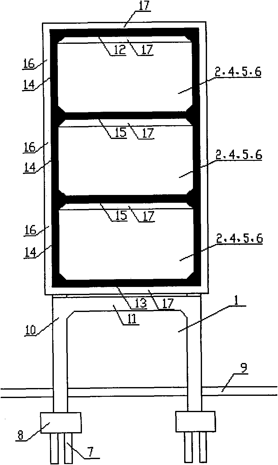
[0098] Embodiment 2: A2-type cross-story beam with grid-shaped cross section
[0099] see figure 2 , A second-layer panel 15 is arranged between the upper flange 12 and the lower flange 13 to form a horizontal single hole and a vertical three-layer beam inner passage, and the web 14 spans the three-layer beam inner passage. All the other are the same as embodiment one.
Embodiment 3
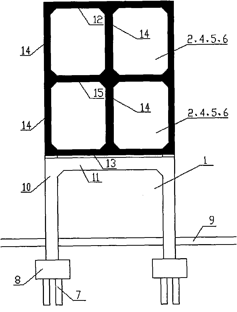
[0100] Embodiment 3: A3-type cross-story beam with grid-shaped cross section
[0101] see image 3 , two webs 14 on both sides and one web 14 in the middle are arranged horizontally, and a layer of panels 15 is arranged between the upper flange 12 and the lower flange 13 to form a horizontal double hole and a vertical two-story beam inner channel, and the beam inner channel Single hole clear width ≥ 3.5m, ≤ 10m. The web 14 is not provided with ribs 16 , and the upper flange 12 , lower flange 13 and panel 15 are not provided with ribs 17 . All the other are the same as embodiment one.
PUM
 Abstract
Description
Claims
Application Information