
Distributing valve for concrete pump and concrete pump

A concrete pump and distribution valve technology, applied in the direction of pumps, piston pumps, pump components, etc., can solve the problems of large rotating matching surface of the structure, enlarge the matching gap between the valve body and the valve core, and shorten the service life of the distribution valve, so as to improve the work efficiency. Reliability, prolonging the validity period of the seal, reducing the effect of power consumption

Active Publication Date: 2010-09-15
SANY AUTOMOBILE MFG CO LTD
View PDF7 Cites 9 Cited by
  • Summary
  • Abstract
  • Description
  • Claims
  • Application Information

AI Technical Summary

Problems solved by technology

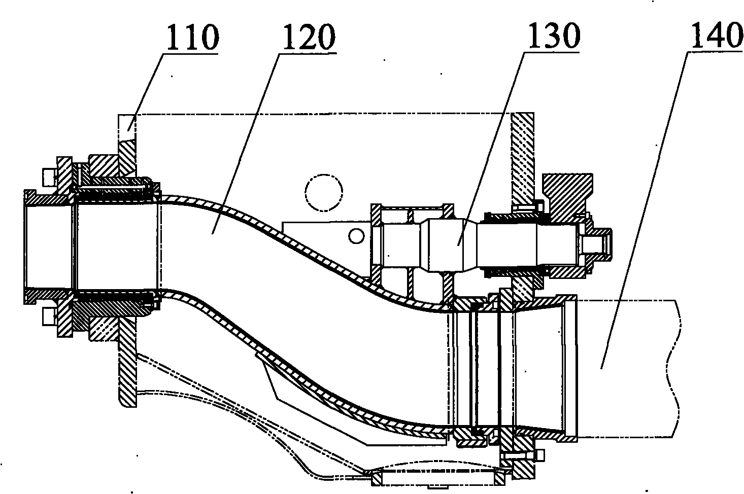
The disadvantage of the S-type distribution valve is that the S-shaped elbow of the S-type distribution valve is located in the hopper 110, occupying a part of the volume of the hopper 110, and will adversely affect the flow of concrete slurry, thereby affecting the suction of the concrete pump performance; at the same time, since the S-shaped elbow is located in the hopper 110, it is easy to accumulate material in the hopper
The above structure makes the distribution valve have a very complex structure, not only the manufacturing process is complex and difficult to manufacture, but also it is difficult to ensure the reliability of the distribution valve
At the same time, the spool can move up and down, and the fit clearance of any stepped surface of the distribution valve can be reflected in the fit clearance of the other stepped surface; therefore, the structure of the upper and lower stepped surfaces will amplify the fit between the valve body and the spool. Clearance shortens the effective life of the seal between the valve body and the valve core, resulting in a shorter service life of the distribution valve
[0010] Since the upper outlet shaft and the lower outlet shaft are respectively rotatably connected to the valve body, the complexity of the structure and the need for sealing make the rotating mating surface between the valve body and the valve core relatively large, thereby increasing the power required for the state transition of the distribution valve; Thereby increasing the power consumption of the concrete pump truck

Method used


Image

  • Distributing valve for concrete pump and concrete pump
  • Distributing valve for concrete pump and concrete pump
  • Distributing valve for concrete pump and concrete pump

Examples


Embodiment 1

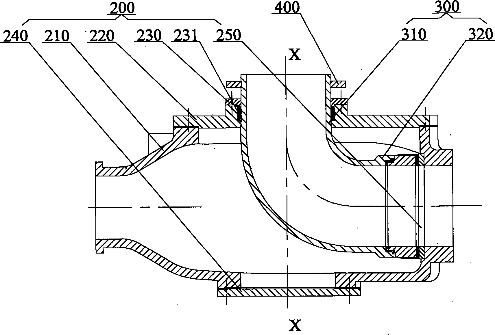
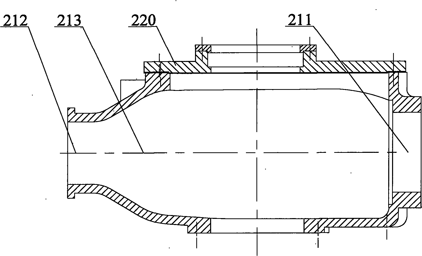
[0044] The distribution valve for a concrete pump provided in Embodiment 1 includes a valve body 200 and a valve core 300 . combine image 3 , the valve body 200 is a shell structure, including a front side wall, a rear side wall, a top wall and a bottom wall, and a cavity is formed inside it, and the cavity is a pumping cavity 213 . The front side wall has an opening 211 opposite to which a wear plate 250 is mounted. The rear side wall has a discharge port 212 connected with a delivery pipe, and the delivery pipe can deliver the concrete slurry to a predetermined position. The top wall includes a cover plate 220, and the cover plate 220 is provided with a feed inlet corresponding to the first pipe section 310; the bottom wall has a discharge plate 240, which can be disassembled or removed when the concrete pump stops running. to remove the concrete slurry lodged in the pumping chamber 213.

[0045] Please refer to Figure 4 and Figure 5 , Figure 4 It is a structural s...


PUM


Abstract

The invention discloses a distributing valve for a concrete pump and a concrete pump. The distributing valve for the concrete pump comprises a valve body and a valve core; a pumping cavity is internally shaped in the valve body and is provided with a discharge hole and a suction hole; wherein the discharge hole is communicated with a delivery pipe and the suction hole is communicated with a delivery tank; a valve core is a L-shaped pipe formed by a first pipe section and a second pipe section, one end of the L-shaped pipe is connected with a hopper and a revolution fitting surface is formed between the end face of the other end of the L-shaped pipe and the internal face and driven by a driving mechanism, the valve core can be switched between a first position and a second position. Compared with the prior art, the distributing valve enjoys the technical effects of simple structure, high reliability, long service life and low manufacturing cost and can meet the demand of delivering concrete slurry under high pressure while reducing power consumption and retaining fine casing capability.

Description

technical field [0001] The invention relates to a concrete pump technology, in particular to a distribution valve for a concrete pump, and also to a concrete pump with the distribution valve. Background technique [0002] Concrete pumps are one of the most widely used concrete machines at present. Concrete pumps generally include hoppers, delivery cylinders, distribution valves and delivery pipes. The hopper is used to store concrete mud, the conveying cylinder is driven by the hydraulic cylinder to perform telescopic movement, and the distribution valve is used to connect the conveying cylinder and the hopper within a predetermined first time, so that the conveying cylinder can absorb material and inhale an appropriate amount of concrete mud; Connect the conveying cylinder with the conveying pipe within a predetermined second time, make the conveying cylinder pump material, press the inhaled concrete slurry into the conveying pipe, and make the concrete mud reach the predet...

Claims


Application Information

Patent Timeline
Patent Type & Authority Applications(China)
IPC IPC(8): F04B53/10F04B15/02
CPCF04B15/023F04B7/0034F04B7/008F04B11/005Y10S417/90
Inventor 易小刚朱红李良荣
Owner SANY AUTOMOBILE MFG CO LTD
Learn More