
Air-conditioning condensed water atomizer

A technology of condensate water and atomizer, which is applied in the direction of preventing condensate water, etc., can solve the problems of improper treatment of condensate water, waste of energy, environmental pollution, etc.

Inactive Publication Date: 2010-09-15
李凯峰
View PDF6 Cites 0 Cited by
  • Summary
  • Abstract
  • Description
  • Claims
  • Application Information

AI Technical Summary

Problems solved by technology

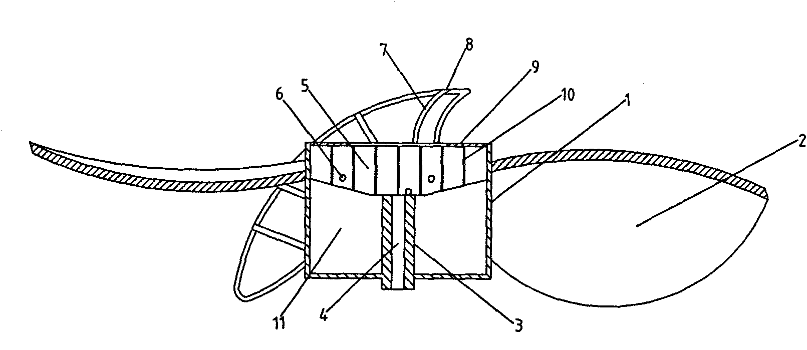
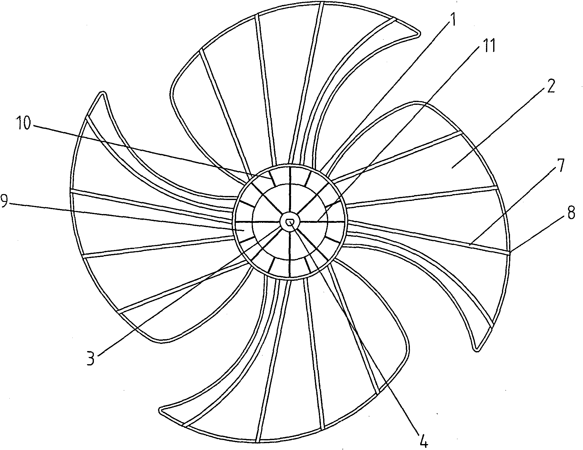
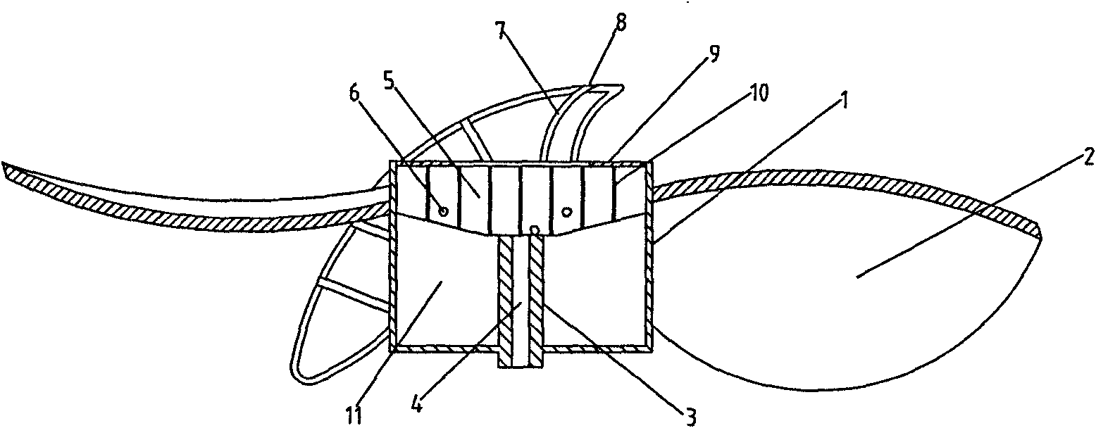
[0003] In view of the above situation, in order to overcome the defects of the prior art, the object of the present invention is to provide an air-conditioning condensate atomizer, which can effectively solve the problems of environmental pollution and energy waste caused by improper treatment of condensate and incomplete evaporation. The technical solution is to include the blade tube and the blades, the blades are evenly distributed on the outer peripheral surface of the blade tube, the inner center of the blade tube has a fixed seat, the motor shaft hole is arranged on the fixed seat, and the inner peripheral surface of the fan blade tube There are multiple equalizing grooves, at least one water outlet hole is provided on the bottom surface of the equalizing groove, and there are multiple water outlet channels extending radially from the fan blade cylinder on the outer peripheral surface of the fan blade barrel, and the inner ends of the water outlet channels are connected with the bottom surface of the equalizing groove. The water outlet holes on the top are connected, and there is a water outlet at the outer end of the water outlet channel. The invention has a novel and unique structure, is convenient to use, and has a good atomization effect. It is an innovation in air-conditioning condensate atomization equipment.

Method used


Image

  • Air-conditioning condensed water atomizer
  • Air-conditioning condensed water atomizer
  • Air-conditioning condensed water atomizer

Examples


Embodiment Construction

[0006] The specific implementation manners of the present invention will be described in further detail below in conjunction with the accompanying drawings.

[0007] Depend on Figure 1-2 Provided, the present invention includes fan blade barrel and fan blade, and fan blade 2 is evenly distributed on the outer peripheral surface of fan blade barrel 1, and fan blade barrel 1 inner center has fixing seat 3, and motor shaft hole 4 is arranged on fixing seat 3, and fan blade There are a plurality of flow equalization grooves 5 on the inner peripheral surface of the barrel 1, and at least one water outlet hole 6 is provided on the bottom surface of the flow equalization groove 5, and there are a plurality of water outlets radiating outward from the fan blade barrel 1 on the outer peripheral surface of the fan blade barrel 1. Channel 7, the inner end of the water outlet channel 7 communicates with the water outlet hole 6 on the bottom surface of the equalizer tank 5, and the outer e...


PUM


Abstract

The invention relates to an air-conditioning condensed water atomizer, which can effectively solve the problems of environment pollution and energy waste caused by improper treatment and halfway evaporation of the current condensed water. The air-conditioning condensed water atomizer is characterized by comprising a blade cylinder and blades, wherein the blades are uniformly distributed on the outer peripheral surface of the blade cylinder; a fixed seat is arranged at the inner center of the blade cylinder; a motor shaft hole is formed on the fixed seat; a plurality of flow equalization grooves are arranged on the inner peripheral surface of the blade cylinder; at least one water outlet hole is formed on the bottom surface of each flow equalization groove; a plurality of water outlet channels which radially extend outwards from the blade cylinder are arranged on the outer peripheral surface of the blade cylinder; the inner end of each water outlet channel is communicated with the water outlet hole on the bottom surface of each flow equalization groove; and a water outlet is arranged at the outer end of each water outlet channel. The air-conditioning condensed water atomizer of the invention has the advantages of novel and unique structure, convenient use and good atomizing effect and is innovation of air-conditioning condensed water atomizing equipment.

Description

1. Technical field [0001] The invention relates to air-conditioning equipment, in particular to an air-conditioning condensed water atomizer. 2. Background technology [0002] Air conditioners are commonly used air-conditioning adjustment equipment. When the air conditioner is refrigerated, condensed water will be generated. The existing condensed water treatment method is to drain it directly, resulting in turbulent flow of condensed water, which not only wastes energy, but also pollutes the environment. In order to solve this problem, the existing technology of attaching condensed water to the cooling fins of the outdoor unit of the air conditioner can improve the cooling effect while evaporating the condensed water, but it cannot fundamentally solve the problem during use. The condensed water cannot be completely evaporated, and the use effect is not good. Therefore, its improvement and innovation are imperative. 3. Contents of the invention [0003] In view of the abo...

Claims


Application Information

Patent Timeline
IPC IPC(8): F24F13/22
Inventor 李凯峰
Owner 李凯峰
Learn More