X-ray phase imaging device

An imaging device and X-ray technology, applied in the field of X-ray optical imaging, can solve problems such as the influence of imaging effect, large influence of imaging quality, and unsatisfactory imaging quality

Active Publication Date: 2010-09-15
BEIJING NORMAL UNIVERSITY
View PDF4 Cites 11 Cited by
  • Summary
  • Abstract
  • Description
  • Claims
  • Application Information

AI Technical Summary

Problems solved by technology

[0004] However, since the polycapillary X-ray optical device is drawn from 200,000 to 300,000 capillaries, the wall of each glass capillary inevitably affects the imaging effect during the imaging process.
Therefore, when using polycapillary X-ray optics for imaging, the background caused by the wall of the polycapillary has a great influence on the imaging quality, and there are major shortcomings, and the imaging quality is still not ideal

Method used


Image

  • X-ray phase imaging device
  • X-ray phase imaging device
  • X-ray phase imaging device

Examples


Embodiment Construction

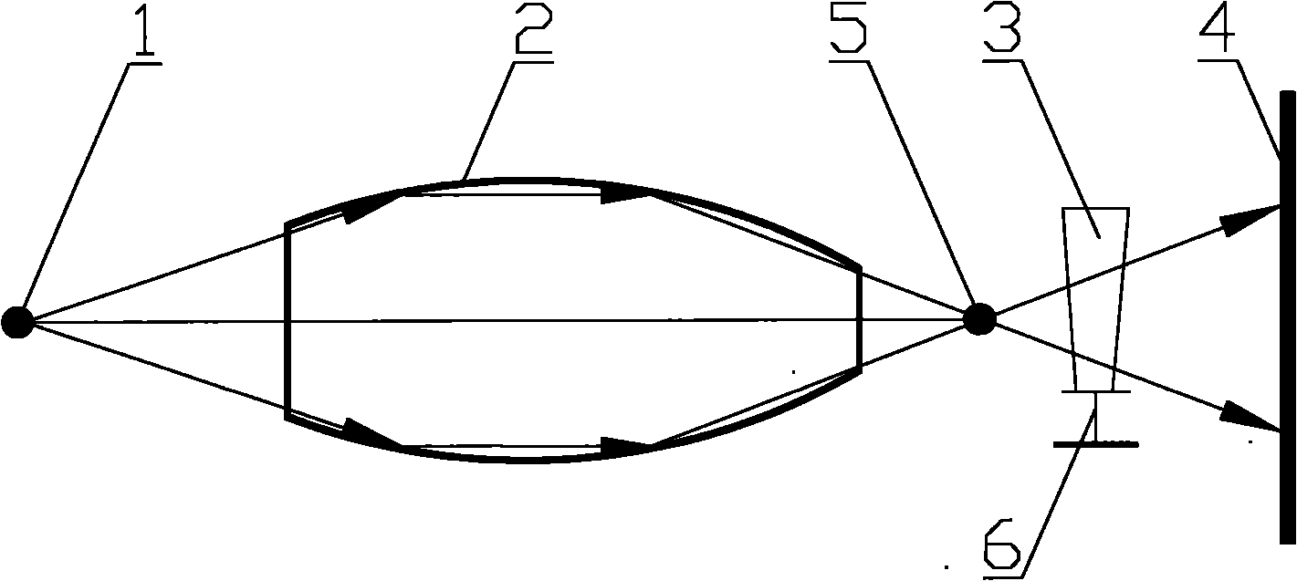
[0022] The core of the present invention is to provide an X-ray phase imaging device. The phase forming device can improve the spatial resolution of the X-ray phase imaging and make the X-ray phase imaging clearer. The device is cheap and easy to popularize.

[0023] In order to enable those skilled in the art to better understand the solution of the present invention, the present invention will be further described in detail below in conjunction with the accompanying drawings and specific embodiments.

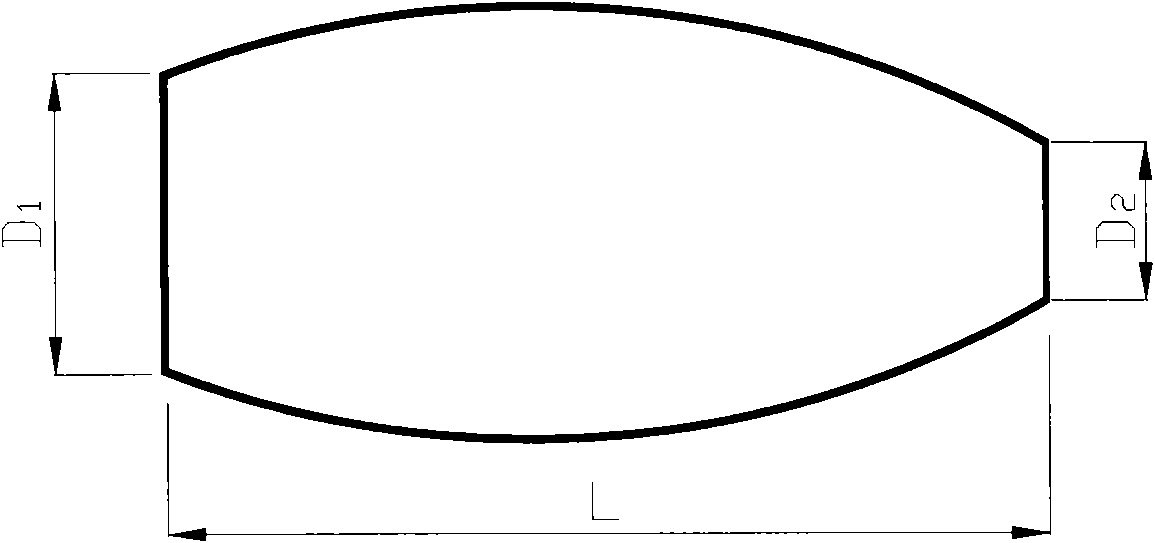
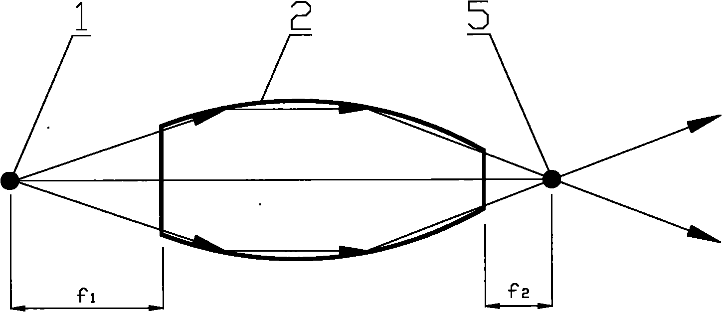
[0024] Please refer to figure 1 , figure 2 and image 3 , figure 1 It is a structural schematic diagram of a specific embodiment of the X-ray phase imaging device provided by the present invention; figure 2 A structural schematic diagram of a specific embodiment of the optical device provided by the present invention; image 3 for figure 1 Schematic diagram of the X-ray path in the shown X-ray phase imaging device.

[0025] The X-ray phase imaging device provided by th...


PUM

PropertyMeasurementUnit
lengthaaaaaaaaaa
diameteraaaaaaaaaa
diameteraaaaaaaaaa

Abstract

The invention discloses an X-ray phase imaging device comprising an X-ray photon source (1), an optical device (2) and an X-ray detector (4) which are sequentially arrayed. An X ray emitted by the X-ray photon source (1) is transmitted from one end of the optical device (2) to the other end of the optical device (2) to form a micro focal spot (5), and after the X ray passes through an imaged sample (3), an image is formed on the X-ray detector (4), and the optical device (2) is a single capillary, the outlet diameter is in the range of 1mum to 30mum. The imaging device can form a smaller micro focal spot in order to increase the spatial resolution of X-ray phase image, the X-ray phase image is clearer, and the X-ray phase imaging device has low cost and is convenient to popularize.

Description

technical field [0001] The invention relates to the field of X-ray optical imaging, in particular to an X-ray phase imaging device. Background technique [0002] The principle of X-ray phase imaging is: using a coherent light source, when the wavefront passes through the object, the coherent (planar or spherical) wavefront is distorted, and when it propagates further, due to the interference effect of the cross-cutting wavefront, there will be an intensity change, Therefore, the phase change can be displayed by the observable intensity change, that is, the phase contrast is formed. There are many kinds of existing X-ray phase imaging systems, one of which uses the continuum emitted by the micro-focus spot X-ray source for phase imaging, and uses the continuum of the X-ray source for imaging, which can shorten the imaging time and improve imaging efficiency. This phase imaging method only requires that X-rays have a high degree of spatial coherence, but not high requirements...

Claims


Application Information

Patent Timeline
Patent Type & Authority Applications(China)
IPC IPC(8): G03B42/02G21K1/00G01N23/04
Inventor 孙天希李玉德刘志国林晓燕罗萍潘秋丽滕玥鹏
Owner BEIJING NORMAL UNIVERSITY
Why Eureka
Try Eureka