Method for automatically identifying LED load light source by using memory chip and implementation device

A memory chip and automatic identification technology, applied in the field of visual inspection, can solve the problems of inconvenient use, high light source temperature rise, and reduce the life of the LED load light source, etc., to achieve the effect of low cost

Inactive Publication Date: 2010-09-15
WAVE CREST SHANGHAI
View PDF7 Cites 15 Cited by
  • Summary
  • Abstract
  • Description
  • Claims
  • Application Information

AI Technical Summary

Problems solved by technology

[0006] However, the biggest disadvantage of the constant voltage power supply is that different types of LED load light sources need to be equipped with corresponding current-limiting resistors on each branch, and the current-limiting resistors, as part of the heat source, are also a major factor that inhibits the efficiency of LED load light sources. The heat loss at the time occupies a considerable share of the calorific value of the LED load light source (the calorific value caused by the current limiting resistor required by different types of LED load light sources accounts for about 15% to 30% of the calorific value of the entire LED load light source), due to current limiting The heating of the resistor causes the entire light source to heat up higher, reducing the life of the LED load light source
[0009] However, the biggest disadvantage of constant current power supply is that LED light sources of different specifications composed of different numbers of LEDs need to use different constant current power supplies.
In this way, the more types of LED load light sources (load changes), the more types of corresponding constant current source power supplies, which will greatly increase the cost of production management, and there is no degree of freedom in use, which will bring great benefits to the use. the inconvenience

Method used


Image

  • Method for automatically identifying LED load light source by using memory chip and implementation device
  • Method for automatically identifying LED load light source by using memory chip and implementation device
  • Method for automatically identifying LED load light source by using memory chip and implementation device

Examples


Embodiment approach

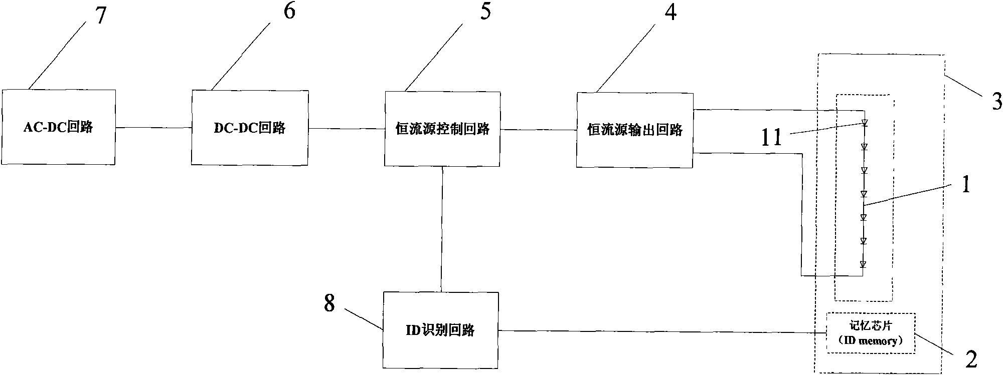
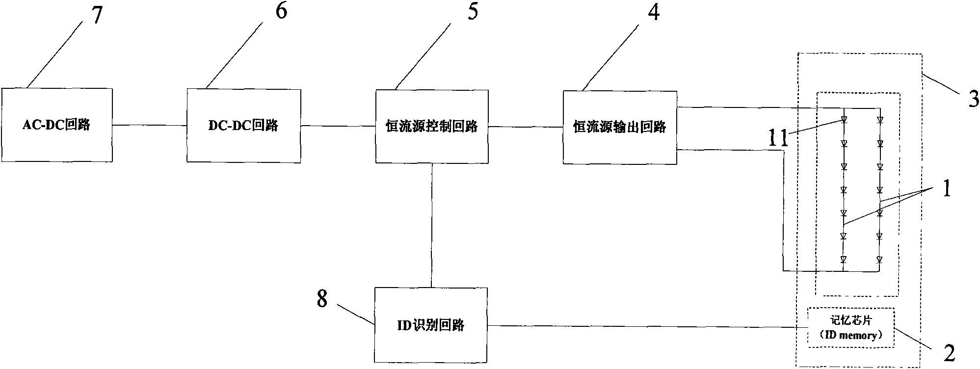
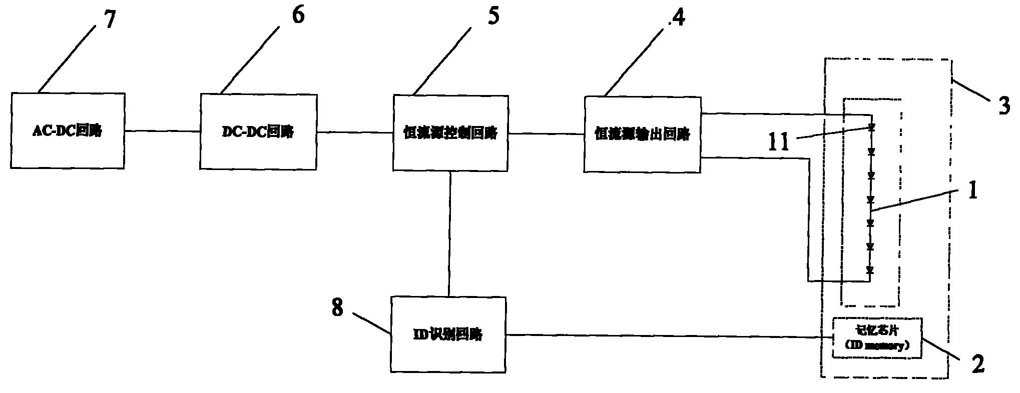
[0024]The implementation method is as follows: the AC-DC circuit 7 of the power supply part converts the public AC voltage of the city network into an available DC voltage; the DC-DC circuit 6 is a DC voltage conversion circuit, and the DC voltage output by the AC-DC circuit 7 is converted into The lower DC voltage provides working voltage for different constant current source control circuits. When one or more LED load light sources 3 are connected to the power supply, the ID identification circuit 8 reads the stored information of the memory chip (ID memory module) 2 in the LED load light source 3, and calculates the constant current according to the connection of the LED load light source 3 The output rating of the source is fed back to the constant current source control loop 5. The constant current source control circuit 5 controls the current output range of the constant current source output circuit 4 (continuously adjustable within 0-rated value) according to the feedb...


PUM


Abstract

The invention discloses a method for automatically identifying an LED load light source by using a memory chip and an implementation device thereof. The device comprises a power supply and an LED load light source, wherein the power supply mainly comprises an AC-DC loop, a DC-DC loop, a constant current source control loop, a constant current source output loop, an ID identification loop, and the like; and the LED load light source mainly comprises an LED branch, an ID memory, and the like. A general constant current control power device which is not limited by LED light source specifications and an LED light source device which is provided with characteristic identification codes have simple manufacture and can greatly reduce product types and lower manufacture and management costs. The LED load light source needs no current-limiting resistor, reduces heat energy generated by the current-limiting resistor, prolongs the service life of products, and maintains the characteristic of good generality. Compared with the common constant current source, the power supply is not only suitable for constant current output to ensure LED luminous efficiency, but also can be suitable for LED load light sources of different specifications, thereby having wider applicability.

Description

Technical field: [0001] The present invention relates to an LED light source device in the field of visual inspection, and more specifically relates to a device that can automatically identify LED load light sources of various specifications by adding a memory chip into the circuit and provide matching power for the corresponding LED load light source. The method, and the circuit device realized according to the method. Background technique: [0002] Today, vision systems have high requirements for light source devices, and different objects to be measured and detection methods have their own matching light sources. There are many types of LED light sources dedicated to image processing, and their power consumption and applicable conditions are also different. The reason is that the arrangement of LED lamps inside the light source is different (series, parallel and series-parallel mixed), the number and type of LED lamps used by each light source are different, and the rate...

Claims


Application Information

Patent Timeline
IPC IPC(8): H05B37/02H02M7/217F21V23/00F21Y101/02
Inventor 邵幼平
Owner WAVE CREST SHANGHAI
Why Eureka
Try Eureka