Cleaning system and method of cleaning bag-like article

A cleaning device and bag-like technology are applied in the direction of cleaning method using liquid, cleaning method using gas flow, cleaning method and utensils, etc., which can solve the problems of time-consuming and inability to clean, and achieve improved cleaning effect and easy cleaning. The effect of preparation and floating position stabilization

Inactive Publication Date: 2010-09-15
WAKA
View PDF1 Cites 10 Cited by
  • Summary
  • Abstract
  • Description
  • Claims
  • Application Information

AI Technical Summary

Problems solved by technology

[0008] In prior art 2, since the five nozzles 232 have to be inserted into the five fingers of the glove respectively, it is a problem to take time in the process of setting
Moreover, because the glove is expanded by the spray pressure of the washing water, the top can be cleaned due to the high spray pressure, but the side cannot be cleaned due to the low spray pressure, which is also a problem.

Method used


Image

  • Cleaning system and method of cleaning bag-like article
  • Cleaning system and method of cleaning bag-like article
  • Cleaning system and method of cleaning bag-like article

Examples


Embodiment 1

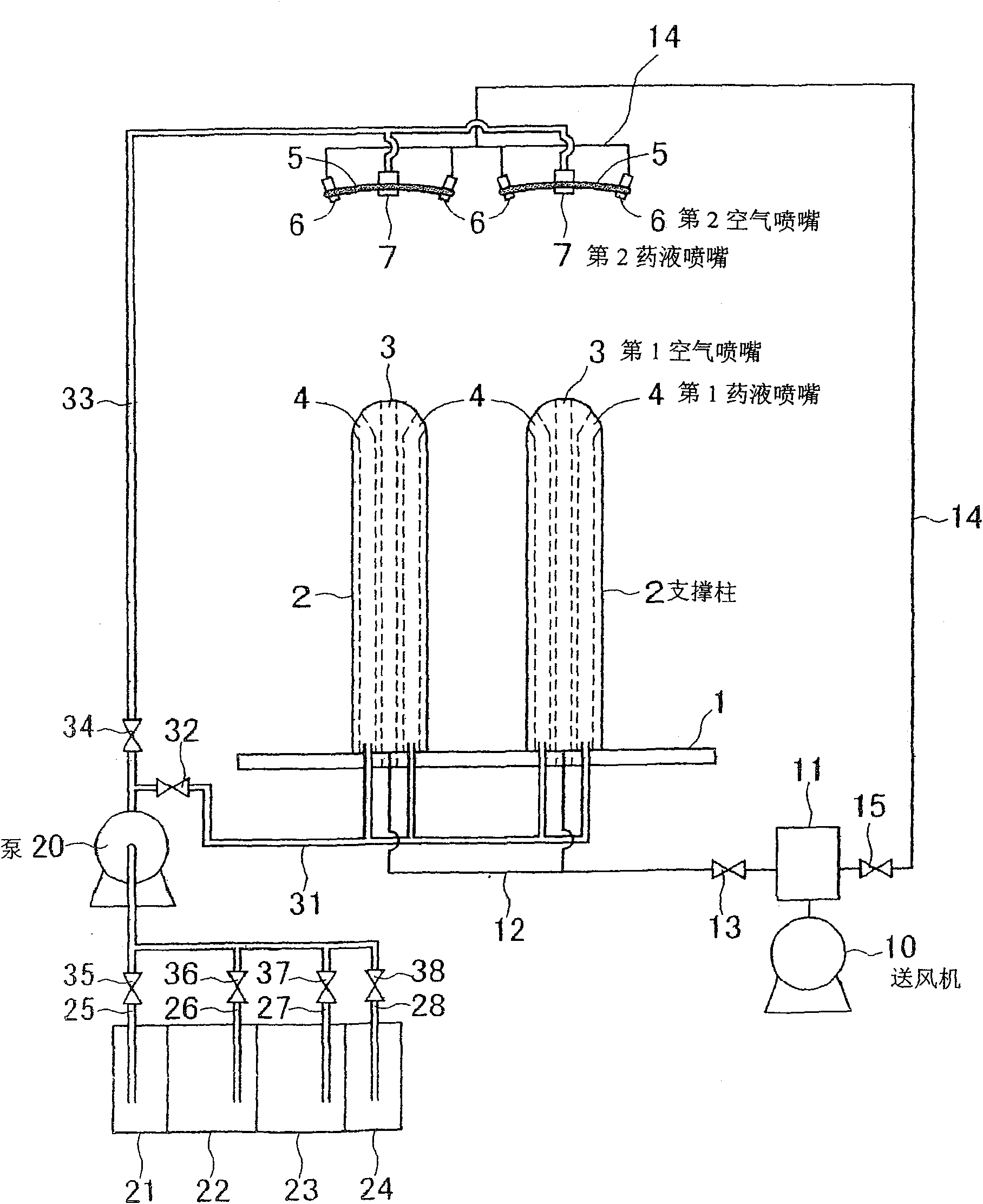
[0047] figure 1 It is an explanatory diagram of the cleaning device related to the state of Embodiment 1 of the present invention.

[0048] exist figure 1 Among them, 1 is an abutment, on which two support columns 2 are arranged. Two support posts 2 are provided to support the left hand and the right hand of a pair of gloves. Each support column 2 is columnar, and the first air nozzle 3 and the first liquid medicine nozzle 4 are hidden inside.

[0049] The aforementioned first air nozzle 3 penetrates the center of the supporting column from top to bottom, and the upper end is open. Therefore, the air can be ejected upward. Furthermore, it can also be used as a nozzle that injects air obliquely upward.

[0050] There are at least 2 first chemical liquid nozzles 4, preferably 3 to 6, extending up and down around the first air nozzle 3, with upper ends slightly inclined outward and open. Therefore, it is possible to eject the liquid medicine or the like obliquely upward. ...

Embodiment 2

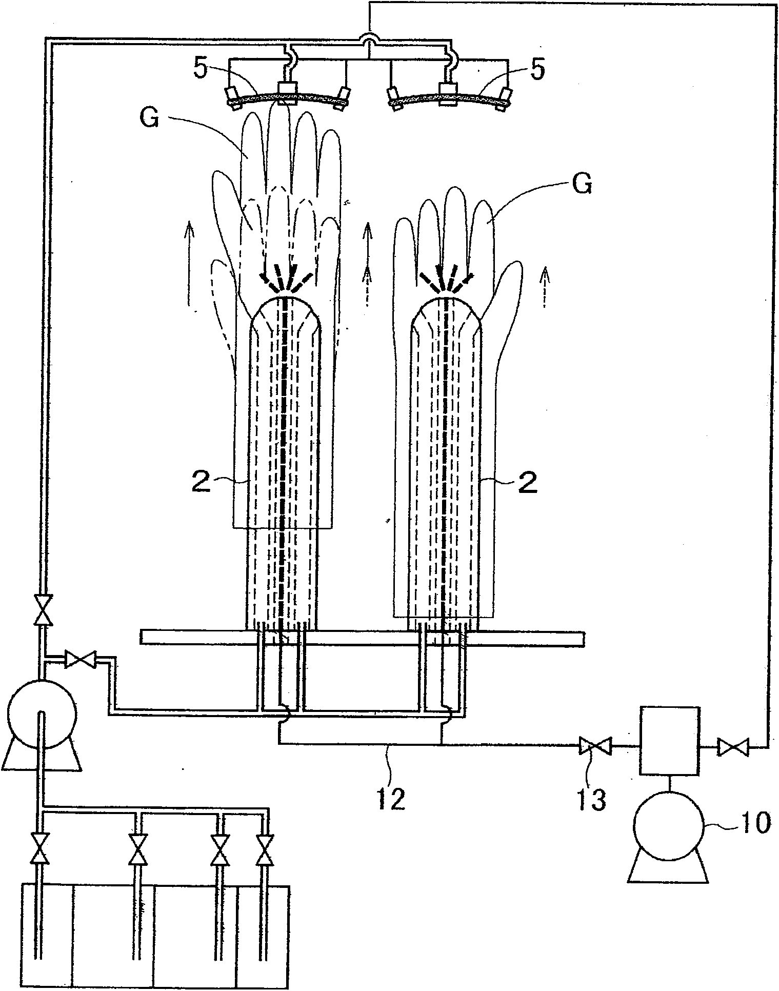
[0097] Figure 7 Shown is the cleaning device related to the state of Example 2.

[0098] The difference of this embodiment is that the structure of the first air nozzle 3 installed on the support column 2 and the structure of the mounting plate 5, and the rest of the structure is the same as the state of the previous embodiment 1, so only the first air nozzle will be described below. 1 Air nozzle 3 and mounting plate 5 are described.

[0099] On the support column 2 of the state of the present embodiment, there are 2 to 3 ejection holes of the first air nozzle 3, and each ejection hole is all facing obliquely upwards, and is arranged clockwise or counterclockwise on the horizontal plane.

[0100] Therefore, the air flow ejected from the first air nozzle 3 is ejected obliquely upward, and swirls around the supporting column 2 to form a swirling flow. This swirling flow is injected into the glove G, and the glove G gradually rises and rotates in the same direction as the swir...


PUM


Abstract

A cleaning device and a cleaning method for cleanly and thoroughly cleaning the outer surface and the inner surface of a bag-like article. A support column (2) has a first air nozzle (3) for ejecting air to the inside of a bag-like article (G), a first chemical liquid nozzle (4) for ejecting chemical liquid, a second air nozzle (6) for ejecting air to the outer surface of the bag-like article (G) supported by the support column (2), and a second chemical liquid nozzle (7) for ejecting the chemical liquid. A blower (10) for supplying air and a heater (11) for heating the air supplied are connected to the first air nozzle (3) and the second air nozzle (6). A chemical liquid supply pump (20) is connected to the first chemical liquid nozzle (4) and the second chemical liquid nozzle (7), and tanks (21, 22) for containing strong alkali electrolysis water or strong acid electrolysis water as the chemical liquid are connected to the pump (20). The bag-like article is cleaned while being floated by pressure of air ejected from the first air nozzle (3) of the support column (2), and this enables the inner surface of the bag-like article to be completely cleaned.

Description

Technical field [0001] The invention relates to a cleaning device for bag-shaped articles and a cleaning method thereof. The bag-shaped article mentioned in this specification refers to such an article whose material is light and thin, and it is difficult for the article itself to maintain its original shape, and the original shape is a bag-like article. Representative of such bag-like items are gloves made of rubber or plastic. The present invention relates to a cleaning device and a cleaning method for cleaning, disinfecting and drying such bag-shaped articles. Background technique [0002] Rubber gloves and plastic gloves are widely used in food processing industry, semiconductor industry, medical field, fishery and other fields. Since these gloves are made of materials with relatively poor air permeability, oil pollution caused by palm sweating and fingerprints has become a major source of pollution. Although it is possible to disinfect the outer surface of the glove ...

Claims


Application Information

Patent Timeline
Patent Type & Authority Applications(China)
IPC IPC(8): B08B3/04B08B5/02
CPCB08B3/02B08B9/00A61L2/035A61B19/04A61L2202/11A61L2202/23A61B2019/048A61B42/60A61B42/00A41D19/0075
Inventor 宫井康行
Owner WAKA
Why Eureka
Try Eureka