Minimum pressure valve

A pressure valve, the smallest technology, applied in the direction of valve details, control valves, valve devices, etc., can solve the problems of increasing spring force, large opening, etc.

Active Publication Date: 2010-09-15
ATLAS COPCO AIRPOWER NV
View PDF0 Cites 4 Cited by
  • Summary
  • Abstract
  • Description
  • Claims
  • Application Information

AI Technical Summary

Problems solved by technology

[0013] The larger opening of the valve (i.e. the larger diameter of the valve body) results in a substantial increase in the required spring force (thus, more serious installation problems due to the larger spring constant, and

Method used


Image

  • Minimum pressure valve
  • Minimum pressure valve
  • Minimum pressure valve

Examples


Embodiment Construction

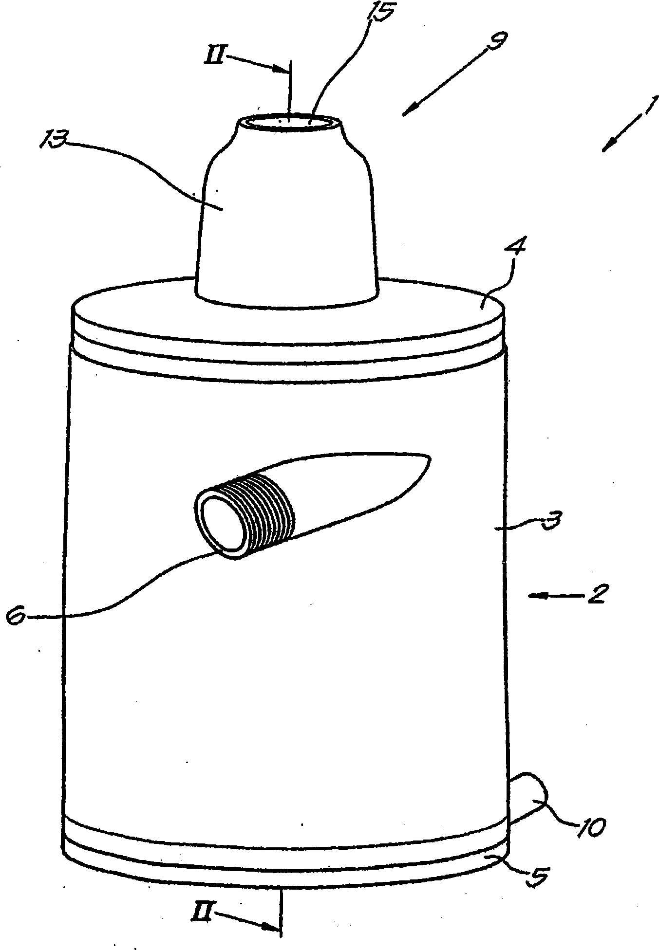
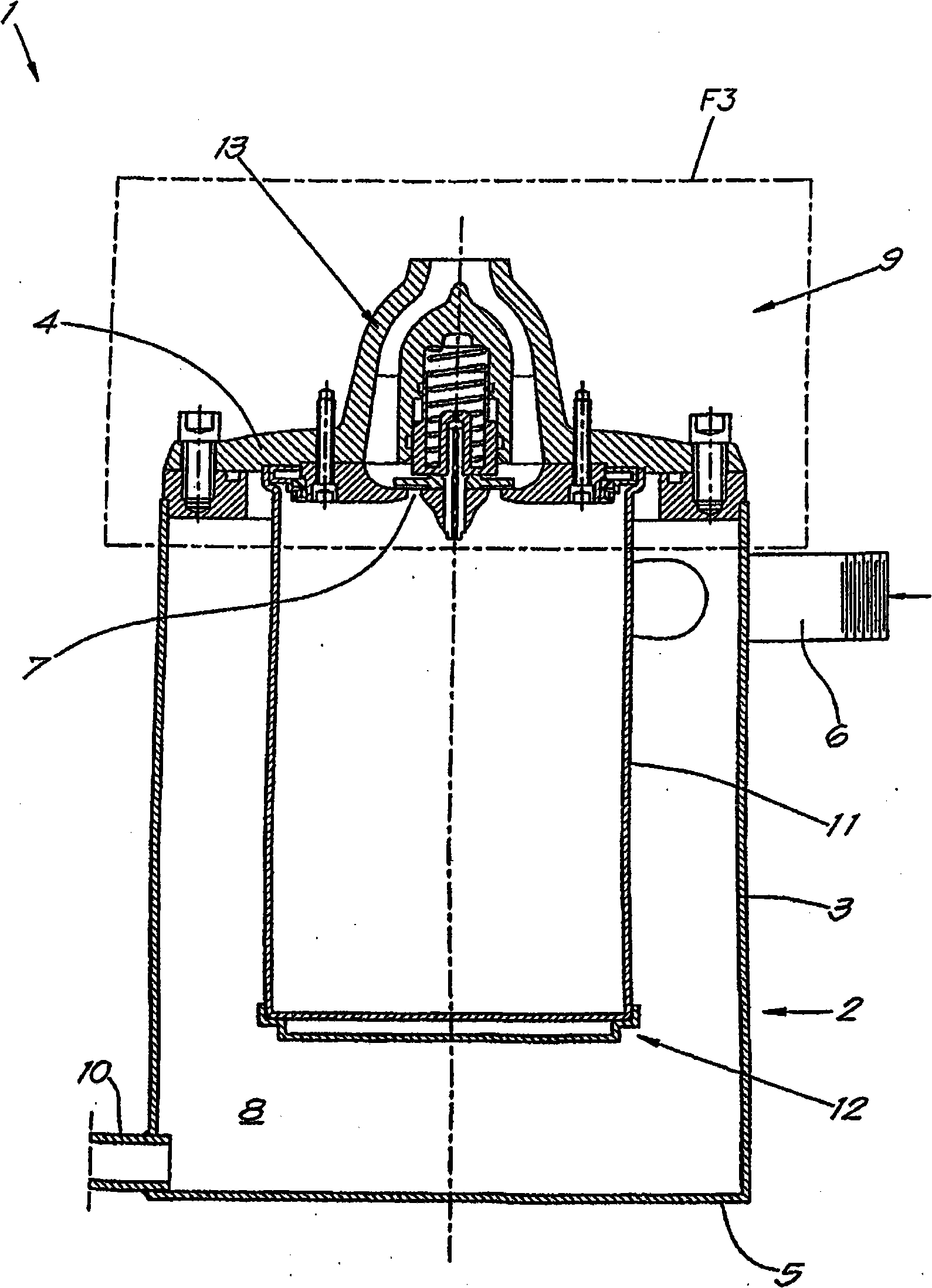
[0034] The figures show a liquid separator 1 provided with a centrifugal separator 2 consisting of a cylindrical housing 3 with an upper wall 4 and a lower wall 5 and a tangential inlet 6 and an axial outlet 7 , The housing 3 defines an inner space 8 .

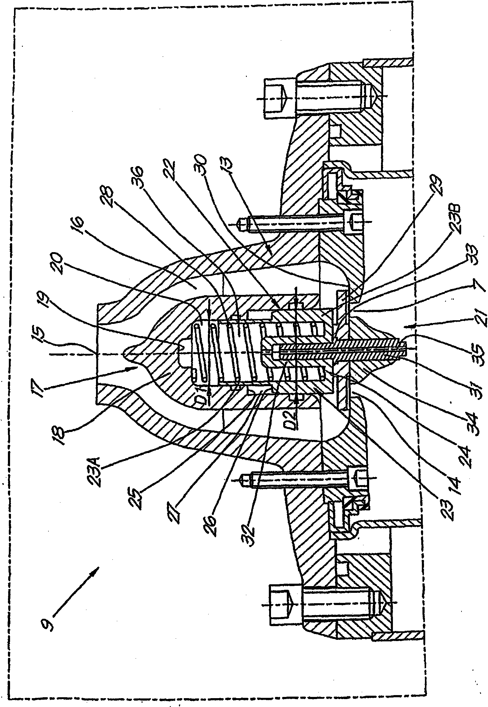
[0035] The aforementioned outlet 7 is preferably arranged in the middle of the upper wall of the housing 3 and is closed by a minimum pressure valve 9 according to the invention, which forms a connection between the space 8 and the tap point for the purge gas.

[0036] In the present example, the centrifugal separator 2 also comprises a drain hole 10 for the separated liquid, preferably located at the bottom of the centrifugal separator 2 in the installed state, on or near the aforementioned lower wall 5 .

[0037] In the present example, a flow-through element 11 (for example in the form of a coalescing filter or another type of fine filter, or in other words able to remove filter for residual droplets).

[0038] In the pre...


PUM


Abstract

Minimum pressure valve having a housing (13) with an inlet (14) and an outlet (15) and in which has been provided a valve body (21) which is pushed against a seating (30) round the inlet (14) in a closed position, and whereby the valve body (21) is situated at a distance from the above- mentioned seating (30) in an open position, such that the inlet (14) is connected to the outlet (15), whereby the valve body (21) is provided in a sliding manner in a valve casing (17) confining, together with the valve body (21) an inner space (36) that is connected to the inlet (14) via a duct (35).

Description

technical field [0001] The present invention relates to minimum pressure valves, in particular for use at the outlet of liquid separators of compressor trains. Background technique [0002] A minimum pressure valve applicable to the outlet of a liquid separator is known, this minimum pressure valve is provided with a housing with an inlet and an outlet connected by an internal piping system whereby the movable valve body is arranged in said piping system, and by spring pressing against the seat surrounding the aforementioned inlet in the first closed state, thereby closing the inlet, while the valve body is located at a distance from the aforementioned seat in the second open state, so that the inlet passes through the piping system to the outlet connect. [0003] The presence of the aforementioned spring ensures that the minimum pressure valve opens only when a certain minimum pressure is reached at the inlet of such a minimum pressure valve, which inlet can be connected e...

Claims


Application Information

Patent Timeline
IPC IPC(8): F16K15/02F16K39/02
CPCF16K39/022F16K15/026Y10T137/7853Y10T137/7852Y10T137/3421Y10T137/7929
Inventor K·A·L·马滕斯
Owner ATLAS COPCO AIRPOWER NV
Why Eureka
Try Eureka