
Lighting system

A lighting system and signal technology, applied in the field of lighting systems, can solve problems such as inability to respond to the movement of objects, and achieve the effects of easy control, low processing power requirements, and low production costs

Inactive Publication Date: 2010-09-15
LITE ON IT
View PDF3 Cites 2 Cited by
  • Summary
  • Abstract
  • Description
  • Claims
  • Application Information

AI Technical Summary

Problems solved by technology

However, such systems cannot respond to the movement of objects to control the light source

Method used


Image

  • Lighting system
  • Lighting system
  • Lighting system

Examples


Embodiment Construction

[0033] In order to make the above-mentioned content of the present invention more obvious and understandable, a preferred embodiment is specially cited below, together with the accompanying drawings, and described in detail as follows:

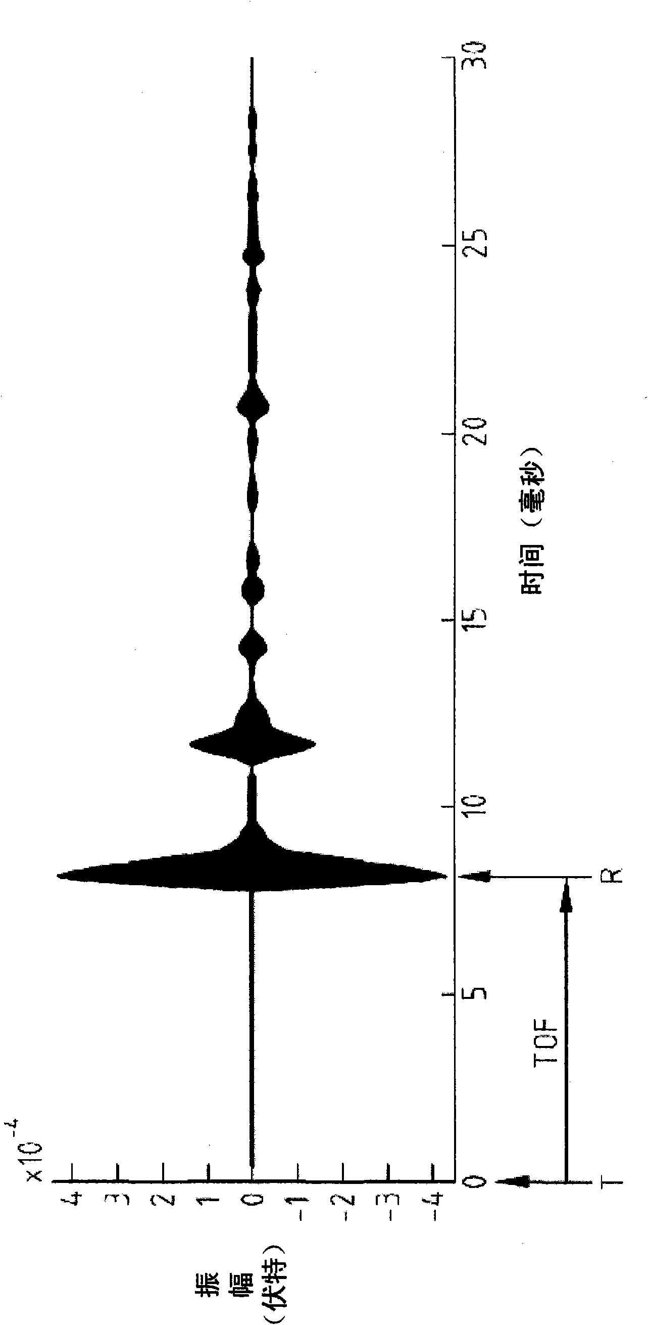
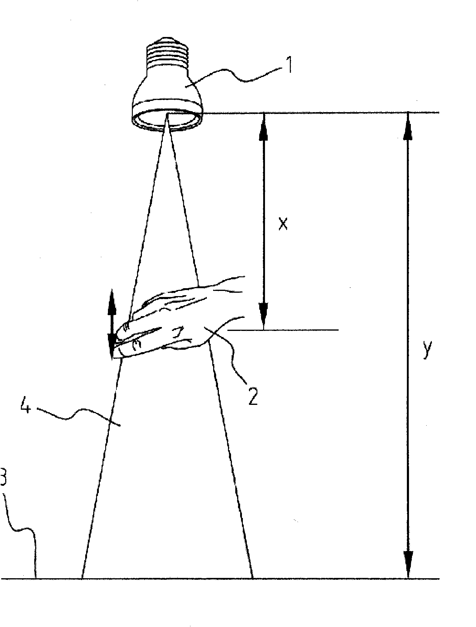
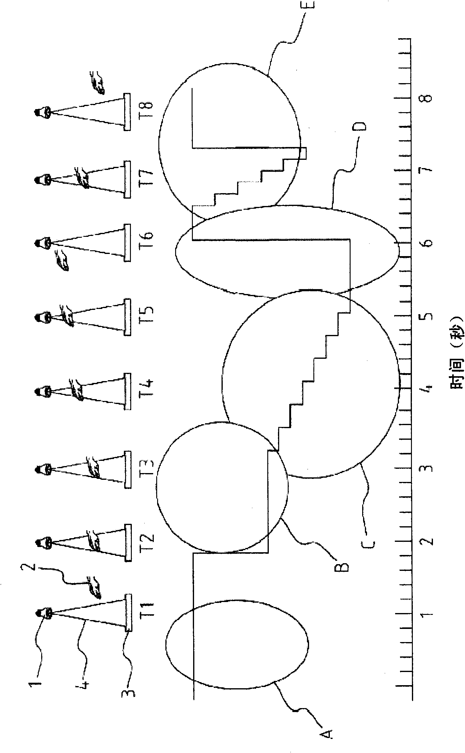
[0034] Such as figure 2 As shown, the lighting system 1 includes a light source and an ultrasonic transmitter and receiver. The ultrasonic transmitter and receiver can be combined into an ultrasonic transceiver or a piezoelectric ultrasonic transceiver. The light source can include multiple light emitting diodes (LEDs), and the ultrasonic transceiver can be built into the center of these LEDs. The lighting system 1 also has a built-in processing device for converting the signal of the transceiver into a control signal, and a control device for adjusting the characteristics of the light source. In a preferred embodiment, the ultrasonic transmitter and receiver transmit and receive ultrasonic signals in the same direction as the light beam of ...


PUM


Abstract

A lighting system comprising a lamp arranged to transform electricity into a light beam having properties such as intensity, colour, colour temperature, direction and beam cone angle; a light control means arranged to adjust said light beam properties; an ultrasonic transmitter arranged to transmit ultrasonic signals; an ultrasonic receiver arranged to receive reflected ultrasonic signals; and a processing means arranged to derive a time-of-flight signal representing the time differences between said transmitted and received ultrasonic signals and to send control signals to said light control means in dependence of said time-of-flight signal, wherein said processing means and said light control means are further arranged to change from adjustment of one of said light beam properties to adjustment of another one of said light beam properties, if a predetermined behaviour in said time-of-flight signal is determined.

Description

technical field [0001] The present invention relates to a lighting system comprising a light source for converting electrical power into a light beam having characteristics such as intensity, color, color temperature, direction and beam cone angle, and a control device for adjusting the light beam characteristics . Background technique [0002] It is well known that the adjustment of lighting characteristics can be achieved through a remote controller (RC). The disadvantage of the remote control is that it must be in the correct position to change the light characteristics. However, there are also many different remote controls that have appeared in the living room for different devices such as TVs, stereos, VCRs, CD / DVDs, game consoles, and recorders. Users may also be confused about the different buttons on many remote controllers, which is extremely inconvenient to use. Even the remote controller and its dedicated receiver will increase the cost of the equipment. [0...

Claims


Application Information

Patent Timeline
Patent Type & Authority Applications(China)
IPC IPC(8): H03K17/00
CPCH03K17/94H05B37/0227H03K2217/94005H05B47/125Y02B20/40
Inventor 汤尼·凡·艾德
Owner LITE ON IT
Learn More