Imaging device and image recording and playback system

一种摄像装置、摄像元件的技术,应用在摄影、立体系统、立体摄影术等方向,能够解决光路弯曲、立体图像摄像控制复杂、色像差等问题,达到视差大小适当的效果

Inactive Publication Date: 2010-09-15
SONY GRP CORP
View PDF1 Cites 27 Cited by
  • Summary
  • Abstract
  • Description
  • Claims
  • Application Information

AI Technical Summary

Problems solved by technology

However, in a prism-type stereo camera, in order to eliminate the overlapping portion of the left and right optical images, it is necessary to form a hood on the prism, which complicates the control at the time of capturing a stereo image.
Also, since the prism utilizes the refraction of the optical axis, and the refractive index is different for each wavelength of light, there is a problem of chromatic aberration
In addition, in the above-mentioned conventional technology, in the path from the optical system to the imaging element, the optical path is bent at places other than the region where the light is parallel light, so when the zooming operation of the photographing lens is performed, the zoom ratio is linked to The optical axis of the ground changes, and there is a problem that the positions of the images on the two imaging elements move relative to each other

Method used


Image

  • Imaging device and image recording and playback system
  • Imaging device and image recording and playback system
  • Imaging device and image recording and playback system

Examples


no. 1 approach

[0023] 1. First Embodiment (Example of Imaging Device)

[0024] 2. Second Embodiment (Example of Video Recording and Playback System)

[0025]

[0026] [Configuration example of imaging device]

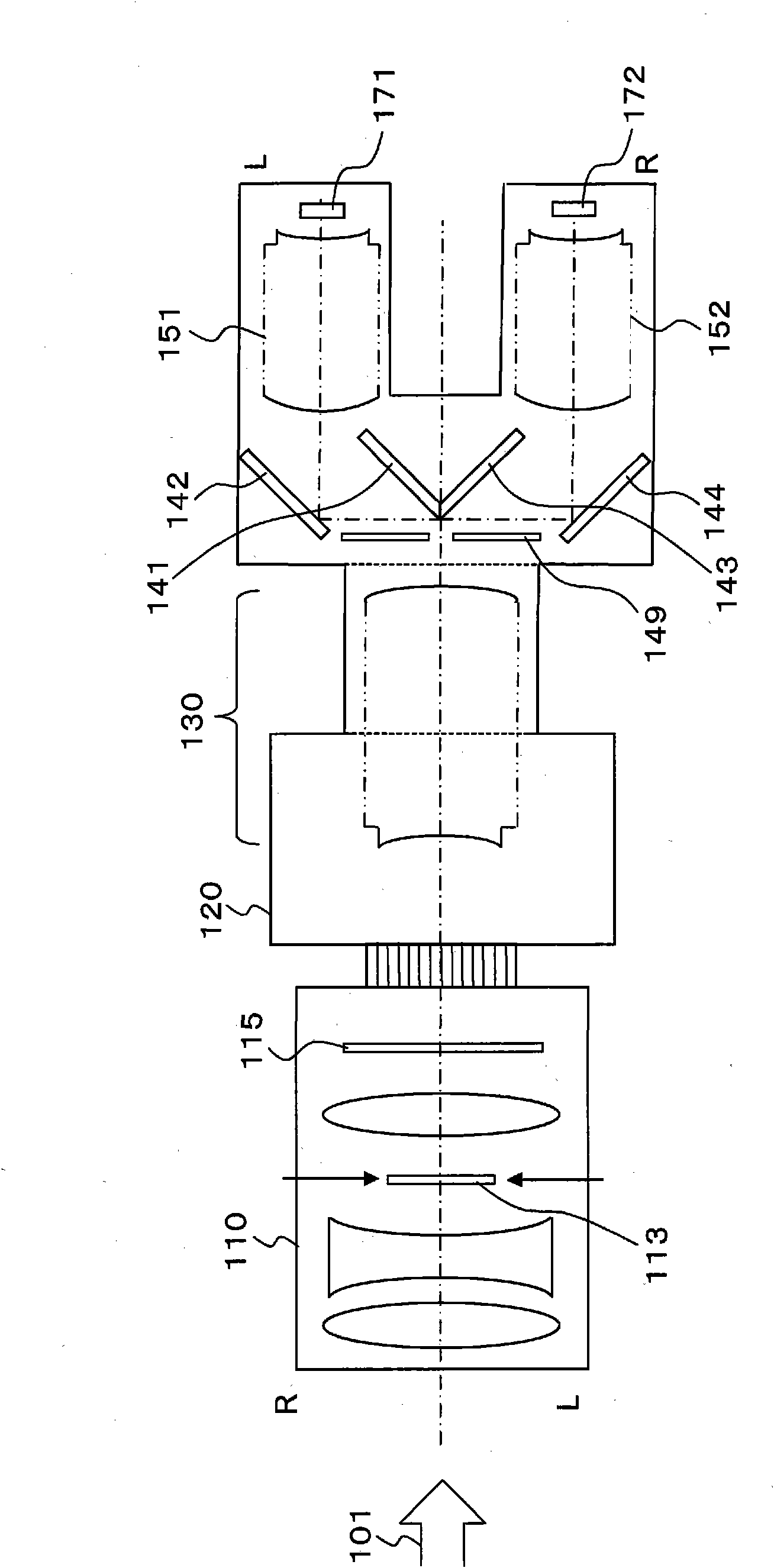
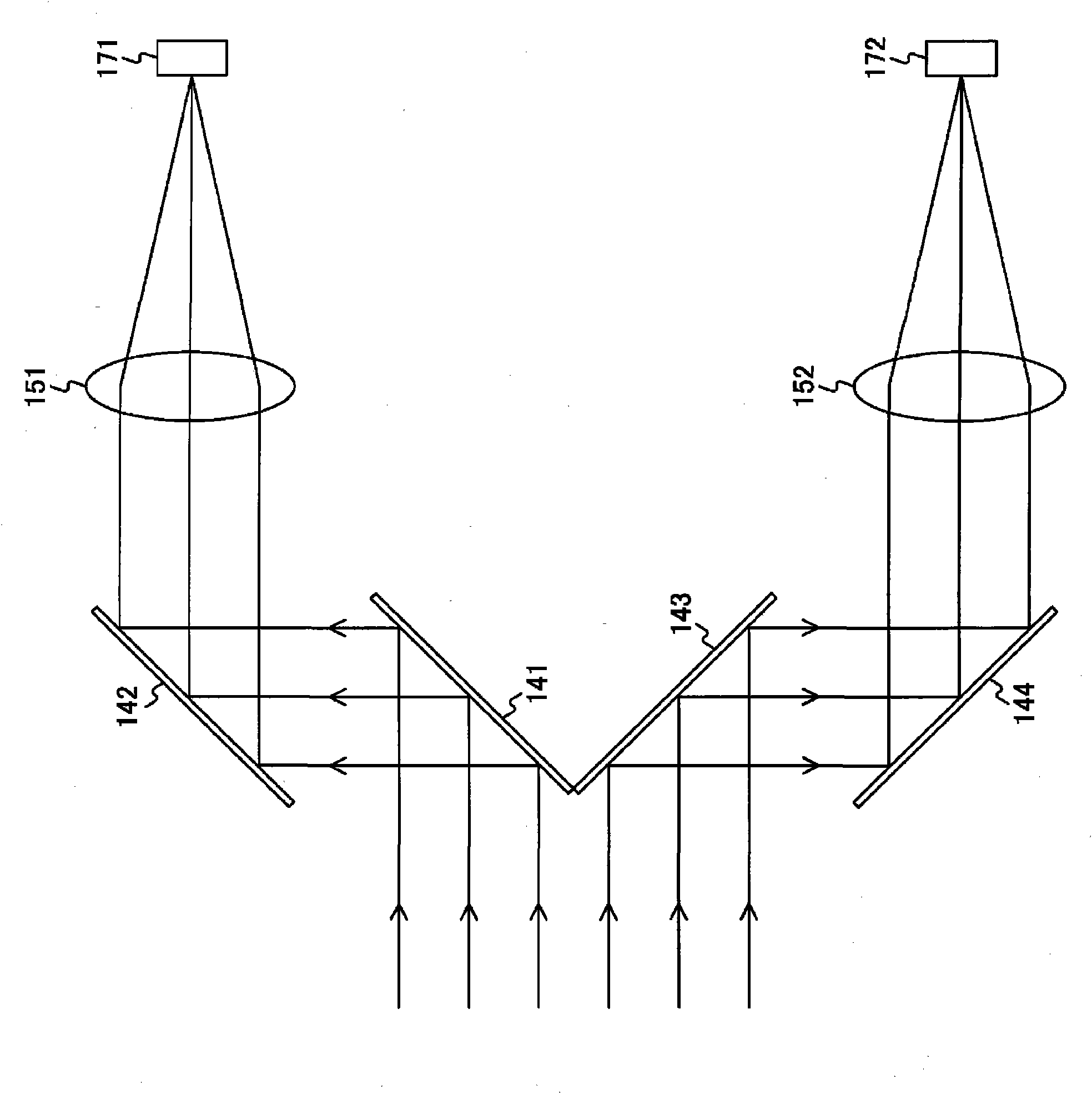
[0027] figure 1 It is a top sectional view of an example of the imaging device in the embodiment of the present invention. This imaging device receives incident light 101 from an object to be photographed, and forms images on left and right imaging elements 171 and 172 to generate left and right video data. The upper part of the drawing is the right direction (R) when facing the subject, and the lower part is the left direction (L) when facing the subject.

[0028] An interchangeable lens 110 is attached to the camera body via a lens frame 120 . The interchangeable lens 110 is a lens group that condenses the incident light 101 from the subject. In addition to a lens group such as a focus lens for focusing and a zoom lens for enlarging the subject, it also has an interchangeable ...

no. 2 approach

[0070] [Configuration Example of Video Recording and Reproducing System]

[0071] Figure 6 It is a diagram showing a configuration example of a video recording and reproducing system according to an embodiment of the present invention. This video recording and playback system includes an imaging unit 100 , a video recording unit 200 , a video storage unit 300 , a video playback unit 400 , and a display unit 500 .

[0072] The imaging unit 100 corresponds to the aforementioned imaging device, receives incident light from an object to be photographed, and generates left and right video data through the left and right imaging elements 171 and 172 .

[0073] The video recording unit 200 records the left and right video data output from the imaging unit 100 in the video storage unit 300 . The video recording unit 200 includes signal processing units 211 and 212 , image memories 221 and 222 , and encoding units 231 and 232 corresponding to left and right video data. The signal p...


PUM


Abstract

High-quality three-dimensional images are picked up with the proper parallax magnitude and minimal chromatic aberration. Light from an imaging subject is split to the left and right by mirrors (141 and 143) in the range where the light diffused from the single point of the subject is parallel light. Light seen from the right facing the subject is reflected by the mirror (141) and then reflected by another mirror (142). Light seen from the left facing the subject is reflected by the mirror (143) and then reflected by another mirror (144). The right-side light reflected by the mirror (142) enters an imaging lens (151). The light incident to the imaging lens (151) forms an image on the light-receiving surface of an image pickup element (171). The left-side light reflected by the mirror (144) enters an imaging lens (152). The light incident to the imaging lens (152) forms an image on the light-receiving surface of an image pickup element (172). Thus, high-quality three-dimensional images are picked up with the proper parallax magnitude and minimal chromatic aberration.

Description

technical field [0001] The present invention relates to an imaging device and a video recording and reproducing system, and more particularly to an imaging device and a video recording and reproducing system that capture an object to be photographed as a stereoscopic image. Background technique [0002] Conventionally, a system has been proposed that simultaneously captures a common subject with two left and right cameras, and displays a stereoscopic image by simultaneously outputting the left and right images. However, in the case of using these two cameras, the size of the device becomes impractical. In addition, the baseline length (baseline) between the two cameras, which is the distance between the eyes of a stereo camera, is not affected by the zoom ratio of the lens, and is mostly about 65 mm, which is equivalent to the distance between the eyes of a person. In this case, the parallax of the zoomed-in video increases, and the visual system is forced to perform inform...

Claims


Application Information

Patent Timeline
Patent Type & Authority Applications(China)
IPC IPC(8): H04N5/225G03B35/08H04N5/92H04N13/02
CPCH04N5/91G03B35/10H04N9/8227H04N13/0239H04N13/0296H04N5/783H04N5/772H04N13/239H04N13/296
Inventor 黑木义彦
Owner SONY GRP CORP
Why Eureka
Try Eureka