Pull-type follow-up bearing device of long lead screw of machine tool

A technology of supporting device and long lead screw, which is applied to feeding devices, metal processing machinery parts, metal processing equipment, etc., can solve the problems of unsuitable precision grinding processing equipment, affecting the quality of the processed surface, and limited supporting rigidity, etc. The effect of machining accuracy and surface quality, maintaining motion stability, and improving motion rigidity

Inactive Publication Date: 2010-09-22
HANGZHOU MACHINE TOOL GROUP +1
View PDF6 Cites 8 Cited by
  • Summary
  • Abstract
  • Description
  • Claims
  • Application Information

AI Technical Summary

Problems solved by technology

This form is limited to improve the rigidity of the support, and there is a blank area of ​​support in the movement of the screw, and the electric and hydraulic linkage is affected by the response speed, which is not suitable for high-speed screw.
In this regard, some machine tools are designed with unpowered auxiliary follow-up support devices. Although the above-mentioned shortcomings are overcome, this unpowered device relies on the movement of the nut seat to drive the auxiliary support to move left and right. The impact brought by the moving parts, especially at high speed, makes the cutting process unstable and affects the quality of the machined surface. It is not suitable for precision grinding equipment

Method used


Image

  • Pull-type follow-up bearing device of long lead screw of machine tool
  • Pull-type follow-up bearing device of long lead screw of machine tool
  • Pull-type follow-up bearing device of long lead screw of machine tool

Examples


Embodiment

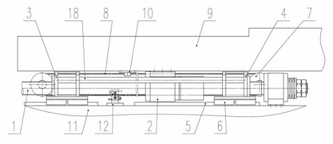
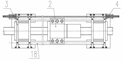
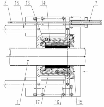
[0017] Example: such as figure 1 , figure 2 As shown, the diameter of the lead screw 1 is 80 mm, the length is 7597 mm (model: 8040-7597-7022-IT5), the nut seat 2 is a HT250 casting, connected with the worktable 9 by screws, and cooperates with the lead screw 1 to form a lead screw transmission pair. There is left follow-up support 4 on the left side of nut seat 2, and right follow-up support 5 is arranged on the right, all are weldment assembly components, also can be integral castings. Traction pulley 7 is housed on the right side of left follow-up support 3, and traction pulley 7 is housed on the left side of right follow-up support 4. Two traction pulleys 7 can rotate around their own axes, and a wire rope 8 with a diameter of 6 mm is set between the two pulleys. One end of the wire rope 8 is fixed on the pressing block 10 of the workbench 9, and the other end is fixed on the pressing block of the bed 11. On the seat 12, the briquetting block 10 and the pressing sea...


PUM


Abstract

The invention discloses a pull-type follow-up bearing device of a long lead screw of a machine tool, which consists of a lead screw, a nut seat, a left follow-up bracket, a right follow-up bracket, a bracket guide rail, a guide rail slider, a traction pulley and the like. The pull-type follow-up bearing device is characterized in that traction wheels are disposed at one side of the left follow-up bracket and the right follow-up bracket respectively; a steel rope is installed on the pulling wheel; one end of the steel rope is fixed on a pressure block on the bottom surface of a worktable, and the other end is fixed on a compaction seat of the machine tool body; and the bottoms of the left and right follow-up brackets are connected with the guide rail slider on the bracket guide rail. The invention not only solves the problem regarding the flexibility of the long lead screw and improves the motion rigidity of a transmission pair, but protects the lead screw and the nut seat against impact during high-speed movement and keeps the motion stability of the transmission pair; therefore, the working stability during precision grinding is ensured and the workpiece processing precision and the surface quality of the workpiece are effectively improved.

Description

technical field [0001] The invention relates to a machine tool transmission mechanism, in particular to a machine tool long lead screw traction type follow-up support device. Background technique [0002] The transmission mechanism of machine tools generally uses screw pair transmission. When the length of the screw is greater than 5 meters, the deflection increases, the rigidity becomes weaker, the motion performance is reduced, and the transmission accuracy of the screw pair is affected. For this reason, an auxiliary support device for the screw is required. There are many kinds of supporting forms in the prior art, some of which are single or multiple supports designed at fixed positions, and electric and hydraulic linkages are adopted. This form is limited to improve the rigidity of the support, and there is a blank area for the support in the movement of the lead screw, and the electric and hydraulic linkage is not suitable for high-speed lead screws due to the influenc...

Claims


Application Information

Patent Timeline
Patent Type & Authority Applications(China)
IPC IPC(8): B23Q5/40
Inventor 管闯徐慧芳陈晓朱瑮林达
Owner HANGZHOU MACHINE TOOL GROUP
Why Eureka
Try Eureka