Horizontal high-temperature vacuum coating production line

A coating production line, vacuum coating technology, applied in the fields of vacuum, electronic spraying, and machinery manufacturing, can solve the problems of restricting the development of solar photovoltaic industry, affecting the uniformity of the coating layer, and the poor high temperature resistance of rubber rollers, etc., to achieve an effective control box The body temperature, the smoothness of substrate transfer, and the effect of extending the service life

Active Publication Date: 2012-07-04
XIANGTAN HONGDA VACUUM TECH CO LTD
View PDF0 Cites 2 Cited by
  • Summary
  • Abstract
  • Description
  • Claims
  • Application Information

AI Technical Summary

Problems solved by technology

The two vacuum coating production lines are distributed with multiple vacuum boxes on the same horizontal plane, and the glass to be coated is transported by the conveying device and processed through each vacuum box to achieve surface coating; in the prior art, the horizontal vacuum The conveying device of the coating production line is to use a conveying track composed of multiple rubber rollers arranged in parallel to realize the conveying of glass. Its carrying capacity is large, the transmission is stable, there is no limit to the size of the glass, and the output is high; however, due to the poor high temperature resistance of the rubber roller, the existing horizontal vacuum coating production line can only be used to produce vacuum coated glass at room temperature
The transmission device of the vertical vacuum coating production line is driven by a stepping motor at the bottom and magnetically guided at the top to realize the transmission of glass; when the glass is transmitted, it is in a state perpendicular to the bottom surface of the vacuum box; the magnetic guidance device The magnetic steel is set on the upper part of the substrate holder carrying the glass, and then the upper part of the substrate holder is snapped into the U-shaped grooves provided with multiple sets of magnetic guide units on the two side walls, and the homopolar repulsion of the magnetic steel is used to realize For the purpose of non-contact positioning and guiding of the substrate rack, it has the advantages of stable transmission, high temperature resistance, no pollution, and high uniformity of the coating layer; Positional accuracy, that is, the position accuracy between the glass and the electron gun is ensured by the magnetic guide structure. In actual use, there are the following problems: First, there is a certain gap between the non-contact magnetic guide U-shaped groove and the substrate holder carrying the glass. Although the homopolar repulsion of magnetic steel can be used to position and guide the substrate holder without contact; because the glass will inevitably shake when it is running, when the glass is high and its own weight is large, its shaking At this time, the non-contact positioning of the magnetic guiding structure and the immediate positioning accuracy of the guiding are significantly reduced, thus affecting the uniformity of the coated film layer
Therefore, the existing vertical vacuum coating production line can only be applied to the production of small-sized TCO coated glass. On the one hand, the output is limited; on the other hand, it restricts the development of the solar photovoltaic industry.

Method used


Image

  • Horizontal high-temperature vacuum coating production line
  • Horizontal high-temperature vacuum coating production line
  • Horizontal high-temperature vacuum coating production line

Examples


Embodiment Construction

[0020] The present invention will be described in further detail below in conjunction with the accompanying drawings and specific embodiments.

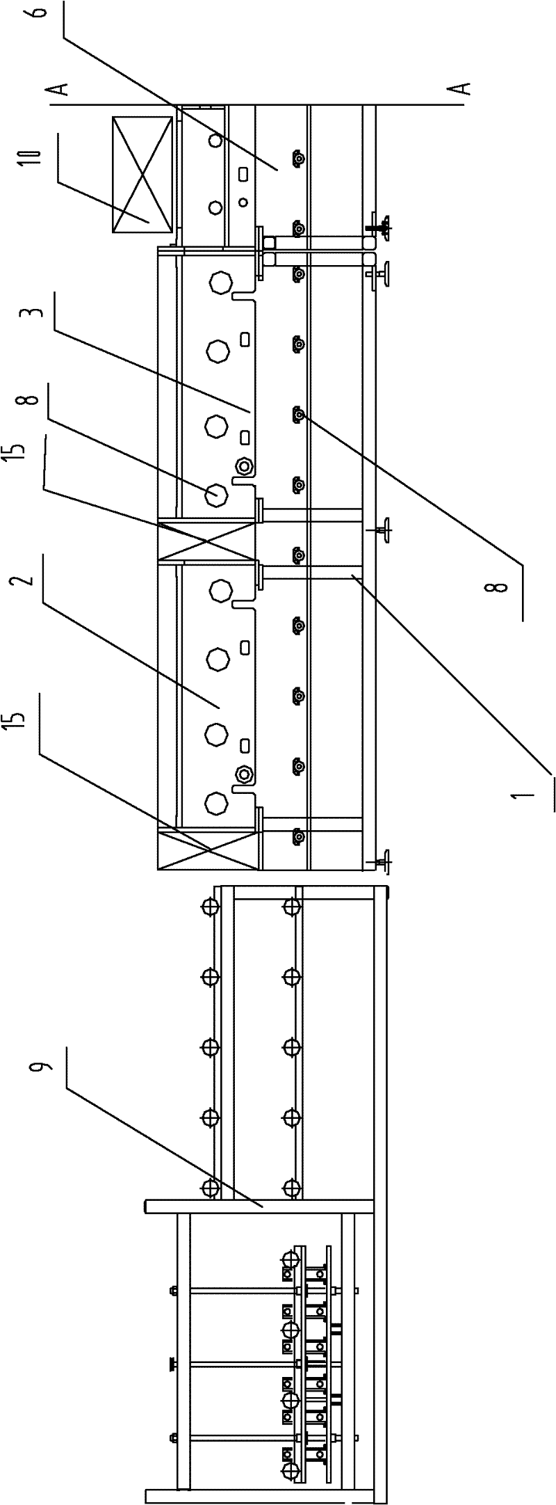
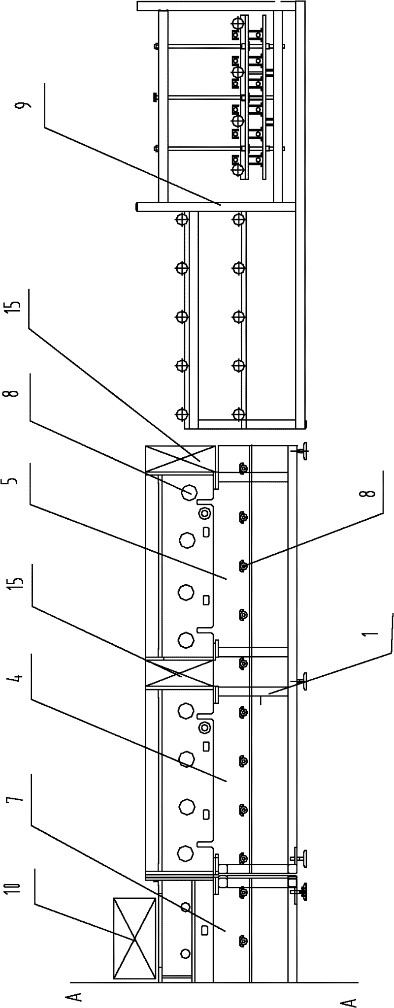
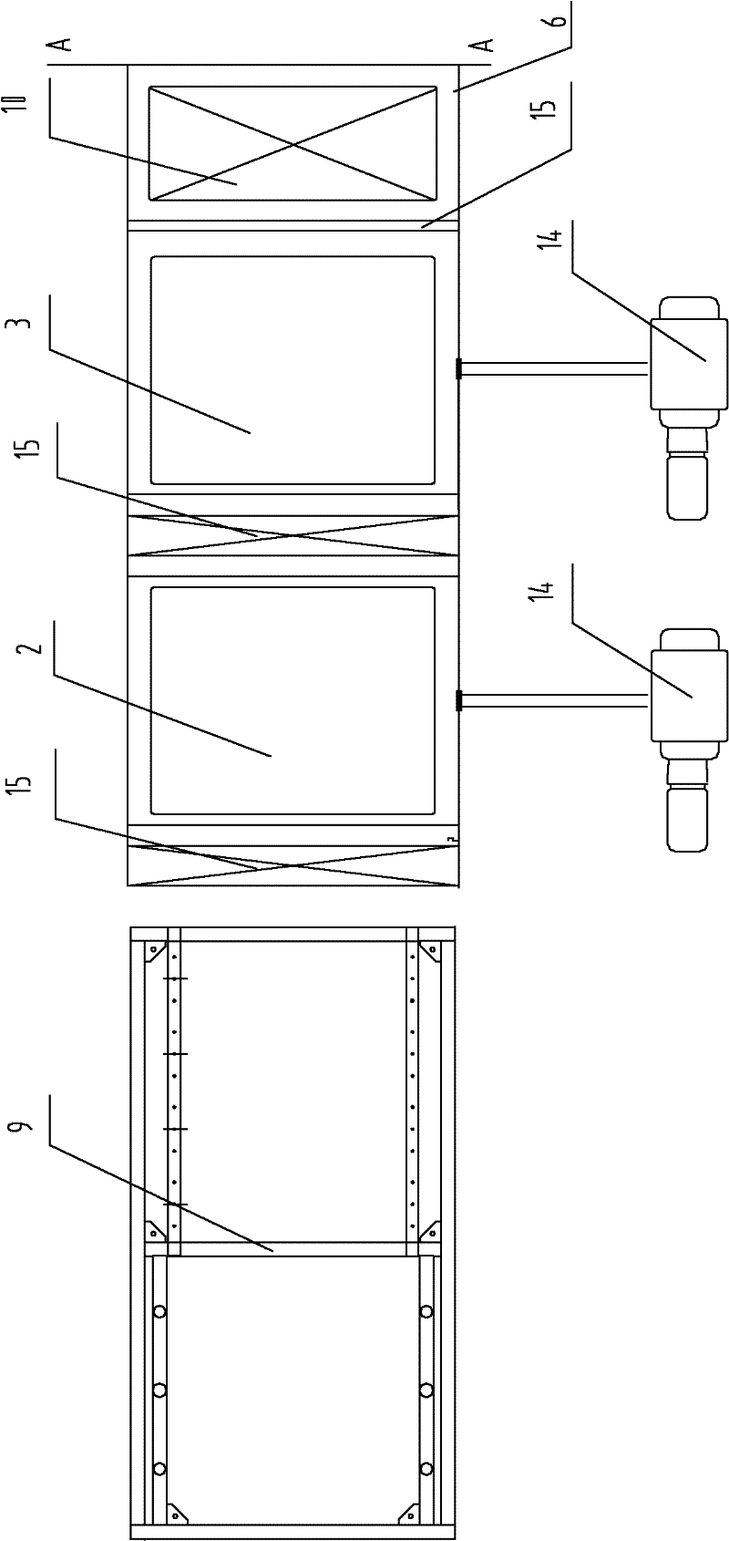
[0021] Referring to accompanying drawings 1, 2, 3, a horizontal high-temperature vacuum coating production line of the present invention includes a frame 1, four vacuum buffer boxes 2, 3, 4, 5, two vacuum coating boxes 6, 7, Substrate rack transfer mechanism 8, automatic loading and unloading sheet mechanism 9, the two vacuum coating boxes 6, 7 are arranged in the middle of the upper part of the frame 1, and the four vacuum buffer boxes 2, 3, 4, 5 Divided into two groups, respectively arranged on the frame 1 at the two ends of the vacuum coating box 6, 7, between the vacuum buffer box 2, 3, 4, 5 and between the vacuum buffer box 3, 4 and the vacuum coating box A pneumatic rotary plate valve 15 is arranged between the casings 6 and 7, and an automatic sheet loading and unloading mechanism 9 is respectively provided at both ends of the ...


PUM


Abstract

The invention provides a horizontal high-temperature vacuum coating production line, which comprises frames, vacuum buffer tank bodies, vacuum coating tank bodies, substrate frame delivery mechanisms and automatic loading and unloading piece mechanisms. The vacuum coating tank bodies are arranged in the middles of the upper parts of the frames; two groups of vacuum buffer tank bodies are arrangedon the frames at the two ends of the vacuum coating tank body respectively; pneumatic rotary plate valves are arranged between the vacuum buffer tank bodies and between the vacuum buffer tank body and the vacuum coating tank body; the two ends of the frames are provided with the automatic loading and unloading piece mechanisms; the lower parts of the frames, the bottoms of the vacuum buffer tank bodies and the bottoms of the vacuum coating tank bodies are provided with the substrate frame delivery mechanisms which are connected with the automatic loading and unloading piece mechanisms; and target guns and heaters are also arranged in the vacuum coating tank bodies. The production line has the advantages of reasonable structure, stable glass delivery, high temperature resistance, suitability for performing high-temperature vacuum coating on the surface of large-size glass, industrial production, and capability of replacing the conventional vertical vacuum coating production line and realizing large-size glass high-temperature vacuum coating.

Description

technical field [0001] The invention discloses a horizontal high-temperature vacuum coating production line, which belongs to the technical fields of mechanical manufacturing, electronic spraying and vacuum coating. Background technique [0002] Coated glass is divided into room temperature vacuum coated glass and high temperature vacuum coated glass. The coated glass used on the exterior wall of a building is usually room temperature vacuum coated glass; the coated glass (TCO) used for solar panels is usually high temperature vacuum coated glass. In the prior art, the vacuum coating production line is divided into a horizontal vacuum coating production line and a vertical vacuum coating production line. The two vacuum coating production lines are distributed with multiple vacuum boxes on the same horizontal plane, and the glass to be coated is transported by the conveying device and processed through each vacuum box to achieve surface coating; in the prior art, the horizont...

Claims


Application Information

Patent Timeline
Patent Type & Authority Patents(China)
IPC IPC(8): C23C14/56
Inventor 黄国兴孙桂红祝海生
Owner XIANGTAN HONGDA VACUUM TECH CO LTD
Why Eureka
Try Eureka