Reduction gear for natural energy recovery system

A technology of recovery system and reduction gear, applied in the direction of transmission, transmission parts, gear transmission, etc., can solve the problems of damage of the third reduction mechanism 530, etc., and achieve the effect of increasing impact resistance

Active Publication Date: 2010-09-22
SUMITOMO HEAVY IND LTD
View PDF8 Cites 4 Cited by
  • Summary
  • Abstract
  • Description
  • Claims
  • Application Information

AI Technical Summary

Problems solved by technology

[0007] However, in the case of reduction gears for systems that recover natural energy, unexpected large loads (radial loads) may be applied from the output side due to wind forces such as high winds and typhoons.
At this time, in the conventional structure, the bearing 544 that receives the radial load is located closer to the motor side than the third reduction mechanism 530 in the final stage, and the large radial load passes through the third reduction mechanism 530, and the third reduction mechanism 530 Mechanism 530 may be damaged, etc.

Method used


Image

  • Reduction gear for natural energy recovery system
  • Reduction gear for natural energy recovery system
  • Reduction gear for natural energy recovery system

Examples


Embodiment Construction

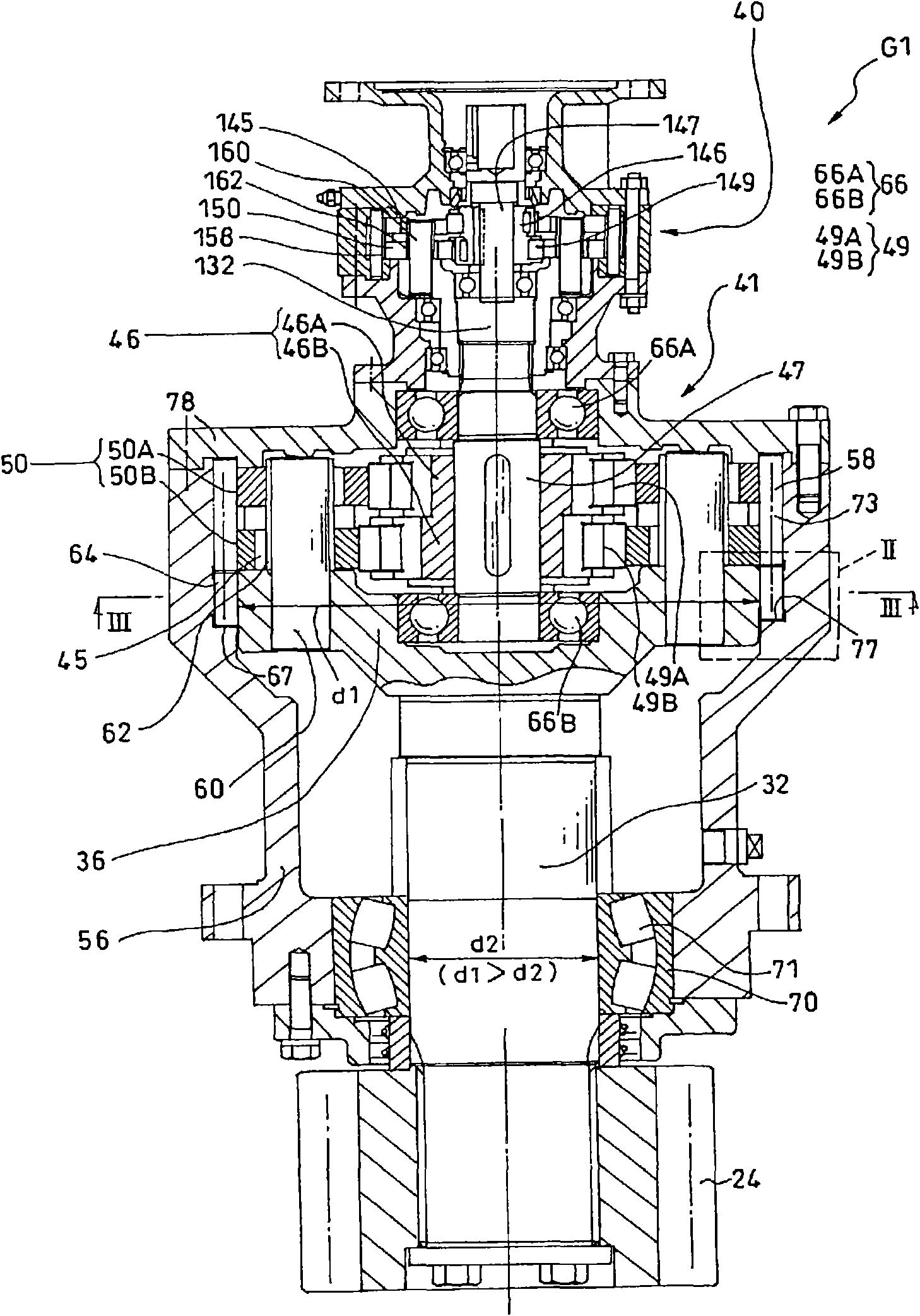
[0023] In order to clarify the use of the reduction gear G1, for convenience, first, a yaw drive device for a wind power generator, which is an example of a natural energy recovery system, will be described. The yaw drive is shown in Figure 6 , Figure 7 .

[0024] In this embodiment, the present invention is applied to the speed reduction device G1 of the yaw drive device 14 . The yaw driving device 14 includes an electric motor Mo, a reduction gear G1 with an output pinion 24 , and a revolving internal gear 28 meshing with the output pinion 24 . Figure 7 In the example of , four reduction gears G1 are depicted, which are respectively fixed on the main body side of the power generating unit 12 . On the other hand, each output pinion 24 of the four reduction gears G1 (refer to figure 1 ) is fixed to the side of the cylindrical support 11, and constitutes an inner ring of a yaw bearing not shown. The outer ring (not shown) of the yaw bearing is fixed to the main body si...


PUM


Abstract

The present invention provides a reduction gear for a natural energy recovery system, which improves the impact resistance in a radial direction and prevent the transmission of radial load caused by external force to a speed reduction mechanism. In the reduction gear (G1) used in a natural energy recovery system, at a part of the reduction gear (G1), which is more next to the output side comparedwith the speed reduction mechanisms (40, 41), an output shaft (32) is supported by a first bearing (68) at the side of the speed reduction mechanisms (40, 41) and a second bearing (70) at the opposite side of the speed reduction mechanisms. Furthermore a shaft diameter (d1) of the part of output shaft (32), which is supported by the first bearing (68), is formed larger than the shaft diameter (d2) of the part that is supported by the second bearing (70).

Description

technical field [0001] This application claims priority based on Japanese Patent Application No. 2009-63621 filed on March 16, 2009. All the content of the application is used in this specification by reference. [0002] The invention relates to a deceleration device for a natural energy recovery system. Background technique [0003] According to Patent Document 1, it is shown in Figure 8 The speed reducer 502 used in the yaw drive device 500 of the wind power generation apparatus shown as an example of the natural energy recovery system is shown. The speed reducer 502 includes a first-stage reduction unit 510 , a second-stage reduction unit 520 connected to the first-stage reduction unit 510 , and a third-stage reduction unit 530 connected to the second-stage reduction unit 520 . [0004] The second-stage reduction unit 520 is constituted by a spur gear type reduction mechanism including an input spur gear 521 connected to the first carrier 507 of the planetary reduction...

Claims


Application Information

Patent Timeline
Patent Type & Authority Applications(China)
IPC IPC(8): F16H1/20F03D7/04F16H1/32F16H57/021
CPCY02E10/722Y02E10/723Y02E10/72
Inventor 峰岸清次
Owner SUMITOMO HEAVY IND LTD
Why Eureka
Try Eureka