Rotor configuration for a rotary valve

A rotary valve and rotor technology, applied in the valve device, valve details, valve shell structure, etc., can solve the problems of reducing the overall volume of the rotary valve, reducing the operating volume and size of the rotary valve, and improving the anti-air leakage capability, enhancing the The effect of operating efficiency

Inactive Publication Date: 2010-09-22
TAIWAN CONTROL VALVE +1
View PDF5 Cites 11 Cited by
  • Summary
  • Abstract
  • Description
  • Claims
  • Application Information

AI Technical Summary

Problems solved by technology

Simply increasing the number of vanes reduces the air leakage problem, but also results in a reduction in the depth of the bag and the overall volume of the rotary valve in order to accommodate welding techniques
The thickness of the blades can be increased when the rotor is manufactured by welding techniques, however, this increase in blade thickness results in a corresponding reduction in the size of the chambers located between the radially extending blades and reduces the operating volume of the rotary valve when feeding granular material into the conduit

Method used


Image

  • Rotor configuration for a rotary valve
  • Rotor configuration for a rotary valve
  • Rotor configuration for a rotary valve

Examples


Embodiment Construction

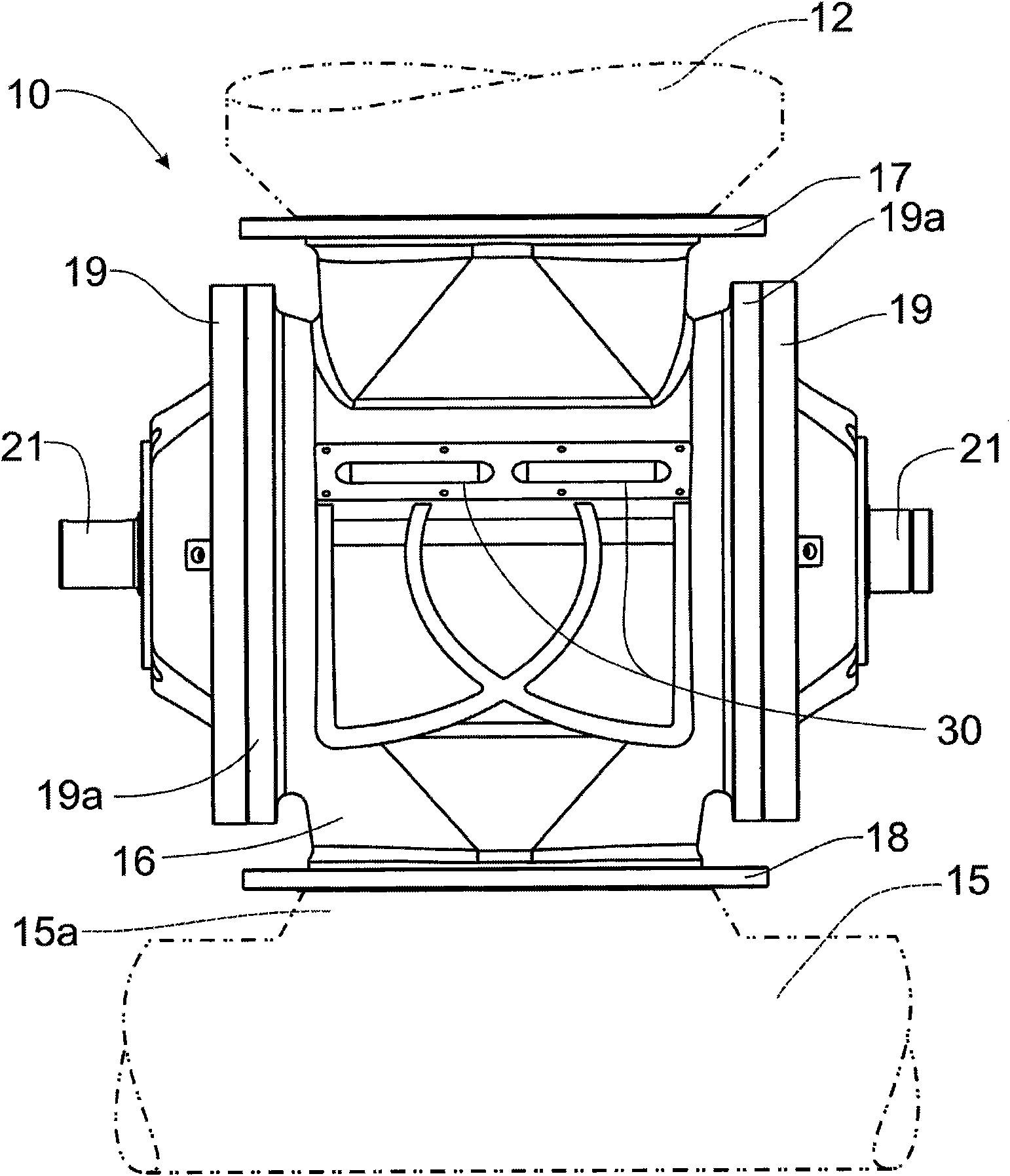
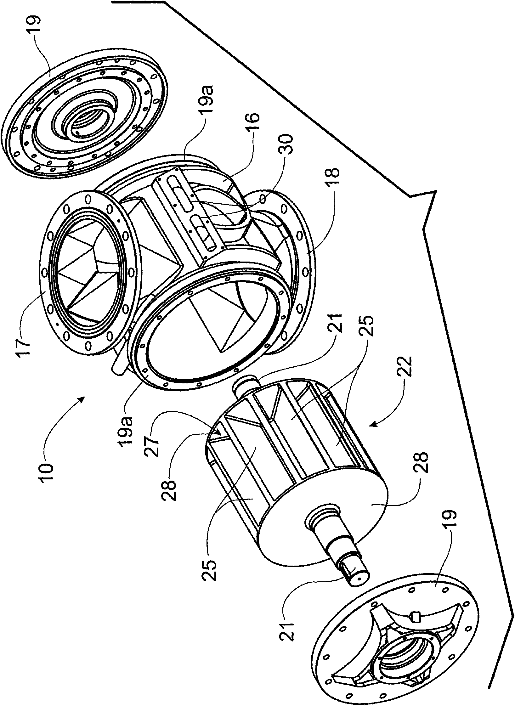
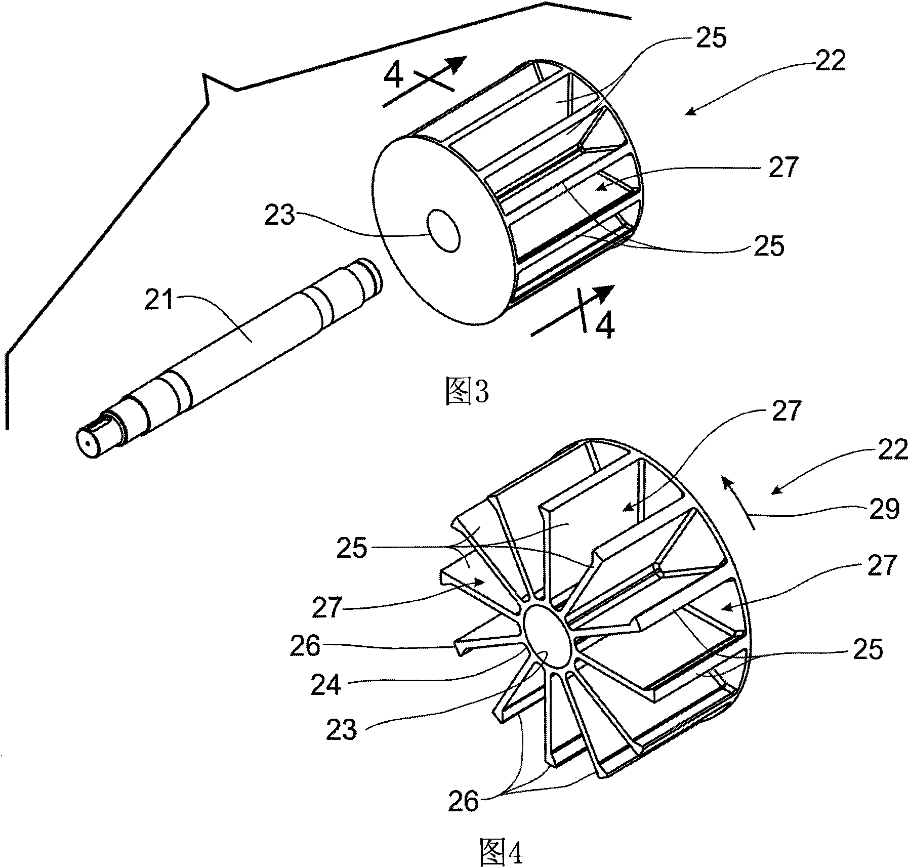
[0032] refer to figure 1 and 2 , which shows a rotary valve in accordance with the principles of the invention. A rotary valve 10 is operatively located between a supply hopper 12 which supplies granular material, such as plastic pellets, etc., which is injected into the conduit 15 of the pneumatic conveying system so that the particles are transported by the pneumatic conveying system Material moves to a distant location. The purpose of the rotary valve is to convey the flowing particulate material into conduit 15 in such a manner that compressed air within the pneumatic conveying system remains within the conduit, thereby providing fluidized particulate material to a remote location. The rotary valve 10 accomplishes this function by operation of an inner rotor assembly 20 having radially extending vanes 25 defining a chamber or pocket 27 therebetween, thereby containing granular material from the supply hopper 12 , and move the particulate material to conduit 15. The end...


PUM


Abstract

A rotary valve for metering the flow of particulate material from a supply source into the air stream of a pneumatic conveying system includes a central rotor manufactured through a precision casting process. The rotor is formed with a plurality of radially extending vanes terminating in tips that are flared circumferentially into the leading side of the vane to provide a flared vane tip that is preferably at least twice the thickness of the vane itself. The valve housing is formed with an elongated release port that has an overall length approximately equal to the length of the pockets formed between adjacent vanes to provide a more complete release of pressurized air from the pocket after the particulate material has been dropped into the pneumatic conveying system. The angled leading edge of the flared tips provides a less aggressive engagement with the particulate material to reduce damage thereto.

Description

[0001] Referenced related application [0002] This application claims domestic priority to US Provisional Patent Application No. 61 / 161,401, filed March 18, 2009, the contents of which are incorporated herein by reference. technical field [0003] The invention disclosed in this application relates generally to rotary valves for conveying particulate material to pneumatic conveying systems, and in particular to rotor arrangements that reduce air leakage on individual rotor blades resulting in air passing through the rotor. Leakage results in less air consumption and further leads to increased operating efficiency as measured by increased volume. Background technique [0004] Rotary valves are well known in the art as a mechanism for introducing a large flow of particulate material into a pressurized pneumatic conveying system. Pneumatic conveying systems use large volumes of compressed air through a pipe or tubular conduit to fluidize large volumes of particulate material ...

Claims


Application Information

Patent Timeline
Patent Type & Authority Applications(China)
IPC IPC(8): F16K5/00F16K5/08
CPCB65G53/4633B65G53/4608B65G65/4881F16K5/0407F16K27/065B65G2201/042B65G2812/1625
Inventor 庄绍炉海因茨·施奈德
Owner TAIWAN CONTROL VALVE
Why Eureka
Try Eureka