Lamb wave virtual time reversal method with high spatial resolution

A technology of virtual time reversal and high spatial resolution, which is applied in the analysis of solids using sound waves/ultrasonic waves/infrasonic waves. It can solve problems such as increasing the width of focused peaks, reducing spatial resolution, and limiting applications, so as to suppress boundary reflections and noise. , improve the signal-to-noise ratio, and improve the effect of spatial resolution

Active Publication Date: 2010-09-22
PLA UNIV OF SCI & TECH
View PDF5 Cites 19 Cited by
  • Summary
  • Abstract
  • Description
  • Claims
  • Application Information

AI Technical Summary

Problems solved by technology

[0005] At present, the Lamb wave time reversal method in the health monitoring of engineering structures mainly has the following two shortcomings: (1) Since the physical time reversal involves two signal transmission and reception, the operation process is cumbersome, and it is difficult for monitoring The requirements for equipment are relatively high, and it is difficult to directly perform physical time reversal in actual engineering; (2) Some researchers have proposed a time reversal focusing method that uses signal operations instead of physical time reversal operations, such as China In the method disclosed in the patent 200710133882.9, the focused enhanced damage scattering signal is as follows Figure 5b As shown, since this method directly calculates the Lamb wave damage scattering signal, it will increase the width of the focused peak and reduce its spatial resolution, which limits the application of this method in the case of multiple damages

Method used


Image

  • Lamb wave virtual time reversal method with high spatial resolution
  • Lamb wave virtual time reversal method with high spatial resolution
  • Lamb wave virtual time reversal method with high spatial resolution

Examples


Embodiment Construction

[0026] The present invention will be further described in detail below in conjunction with the accompanying drawings and specific embodiments.

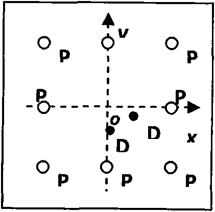
[0027]In this example, the LY-21CZ aluminum plate commonly used in engineering structures is used as the structure to be tested. A circular magnet (diameter 10 mm, thickness 3 mm) was used to simulate two tiny damages D1 and D2 in the structure. Establish a Cartesian coordinate system with the center of the aluminum plate as the coordinate origin, then the distribution and position of the piezoelectric film and damage in the coordinate system are shown in figure 1 and Table 1. The monitoring equipment consists of waveform generation and data acquisition system, power amplifier and matrix switch controller. Among them, the LAI200-ISA arbitrary waveform generation card, signal amplification card and PCI-9812 data acquisition card in the waveform generation and data acquisition system respectively realize the functions of Lamb wave ex...


PUM


Abstract

The invention provides a lamb wave virtual time reversal method with a high spatial resolution. The method comprises the following steps: (1) a piezoelectric array consisting of n piezoelectric chips is arranged on a structure to be tested, (2) an injury scattering path transfer function is obtained, (3) multipath injury scattering signals are obtained and (4) focused and strengthened injury scattering signals are obtained through virtual time reversal processing. Compared with the prior art, the invention has the technical effects: (1) complex physical time reversal operation is unnecessary, the requirement on a monitoring device is low, and the operation is easy, (2) the multipath injury scattering signals are focused and strengthened at the corresponding injury part, boundary reflection and noise are prohibited and the signal-to-noise ratio of the injury scattering signals is improved effectively, and (3) the time domain of the wave crest of Lamb wave and the spatial resolution ratio of injury focus wave crest is improved.

Description

technical field [0001] The invention relates to a Lamb wave virtual time reversal method with high spatial resolution, belonging to the technical field of engineering structure health monitoring. Background technique [0002] Engineering structure health monitoring technology is an online, dynamic and real-time monitoring technology, which has developed rapidly in recent years and plays an increasingly important role in the safety and reliability assessment of engineering structures. Lamb wave, as a kind of ultrasonic guided wave propagating in plate structure, has received increasing attention in the field of structural health monitoring because it can propagate over long distances and is sensitive to both surface and internal damage of structures. At present, the structural health monitoring technology based on Lamb wave, especially the active Lamb wave monitoring technology has become a research hotspot. This technology can be divided into four processes: ① excite the pi...

Claims


Application Information

Patent Timeline
Patent Type & Authority Applications(China)
IPC IPC(8): G01N29/04
Inventor 石立华蔡建邵志学邵哲
Owner PLA UNIV OF SCI & TECH
Why Eureka
Try Eureka