Novel electromechanical automatic feeding device

A feeding device, electromechanical technology, applied in the direction of conveyors, conveyor objects, transportation and packaging, etc., can solve the problems of high labor intensity, poor interchangeability, complex structure, etc., to achieve precise control and adjustment, easy production matching, and structural simple effect

Inactive Publication Date: 2010-09-29
郑合新
View PDF0 Cites 15 Cited by
  • Summary
  • Abstract
  • Description
  • Claims
  • Application Information

AI Technical Summary

Problems solved by technology

[0002] At present, in the production of some industries, a large number of parts with the same specifications must be sent to specific machining parts. For example, in the stamping industry, blank materials or semi-finished parts must be sent to the press mold for processing. After the drug bottle caps are regularly sent to a specific position, the moisture-proof paper pad is pressed into the bottle caps, and the workpieces are regularly put into the conveyor be

Method used


Image

  • Novel electromechanical automatic feeding device
  • Novel electromechanical automatic feeding device

Examples


Embodiment Construction

[0008] The specific embodiment of the present invention will be described in detail below in conjunction with the accompanying drawings.

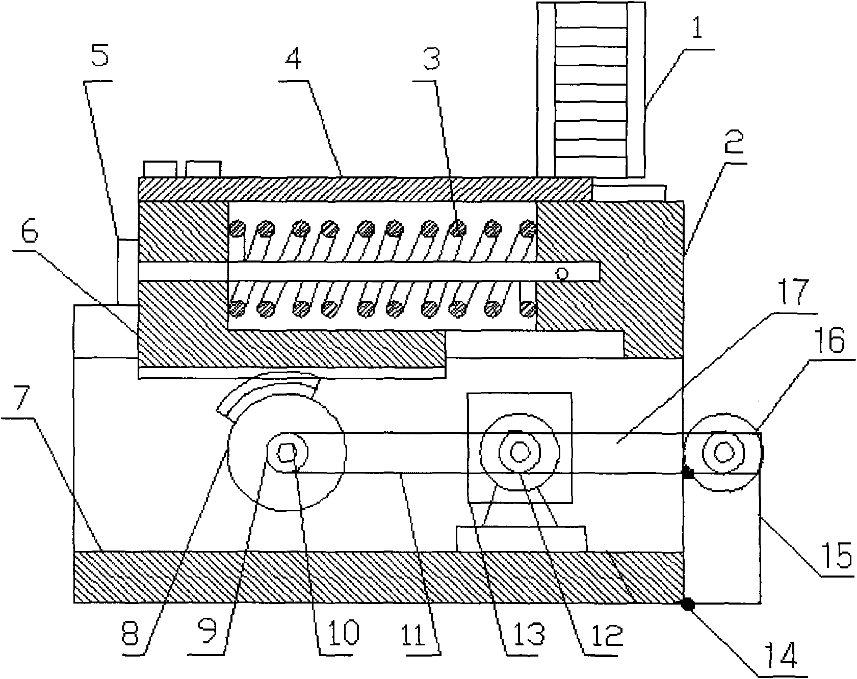
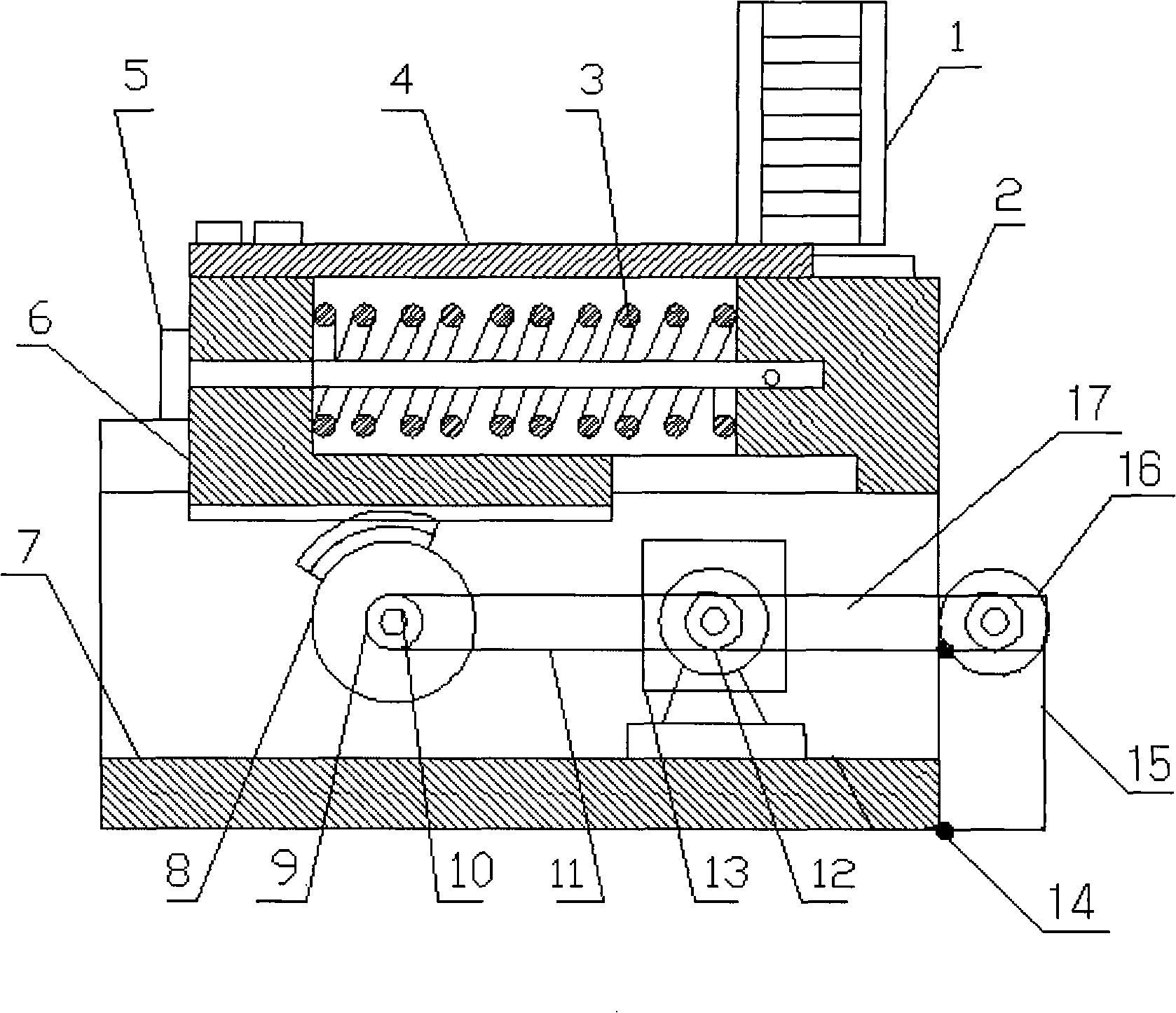
[0009] Install and fix the hopper (1) on the appropriate position of the hopper seat (2), insert the guide post (5) into the hole of the elbow part of the rack (6), and at the same time put the return spring (3) on the guide post ( 5) on the top, then install the rack (6) into the guide rail a of the frame (7), and at the same time fix the right end of the guide post (5) on the hopper seat (2) with pins or screws or other methods, during assembly It should be ensured that the rack moves smoothly in the guide post (5) and guide rail a, and the return spring (3) should be properly compressed. In the above cases, the pusher plate (4) can be installed. Drive shaft (10) is installed on the place where frame (7) is perpendicular to the direction of motion of rack (6), and tooth-missing gear (8) and passive chain (9) are installed on drive shaft (...


PUM


Abstract

The invention discloses a novel electromechanical automatic feeding device. A hopper is arranged and fixed at a proper position of a hopper seat; a guide post is penetrated into a hole of a rack elbow; a return spring is sleeved on the guide post, and then a rack is arranged in a guide rail of a machine frame; the right end of the guide post is fixed on the hopper seat by using a pin or a bolt and other methods; and during assembling, the rack should be ensured to move smoothly in the guide post and the guide rail, the return spring is compressed appropriately, and a pushing plate is arranged on the feeding device. A driving shaft is arranged at a position vertical to the moving direction of the rack on the machine frame; a tooth-missed gear and a driven chain are arranged on the driving shaft; the rack is ensure to be meshed with the tooth-missed gear, and also the rack is ensured to be able to quickly and accurately reset under the action of the return spring after the meshed gears do not contact each other; and the driving parts such as a frequency conversion speed-adjusting motor, a speed changer, a driving chain wheel, a motor chain wheel, a chain, a motor chain and the like are arranged in the feeding device in turn and are fixed by fixing bolts.

Description

technical field [0001] The invention relates to an automatic feeding device, in particular to a novel electromechanical automatic feeding device. It belongs to the technical field of mechatronics. Background technique [0002] At present, in the production of some industries, a large number of parts with the same specifications must be sent to specific machining parts. For example, in the stamping industry, blank materials or semi-finished parts must be sent to the press mold for processing. After the drug bottle caps are regularly sent to a specific position, the moisture-proof paper pad is pressed into the bottle caps, and the workpieces are regularly put into the conveyor belt in the assembly line, etc. Traditionally, these materials are delivered manually or in their respective production fields. The method of special feeding mechanism and the method of manual feeding are not only labor-intensive, but also difficult to maintain consistent production beats. The use of a...

Claims


Application Information

Patent Timeline
IPC IPC(8): B65G25/08B65G47/82
Inventor 郑合新
Owner 郑合新
Why Eureka
Try Eureka