Cement concrete pavement joint dislocation detection device and method based on binocular vision

A cement concrete, binocular vision technology, applied in measuring devices, optical devices, roads, etc., can solve the problems of accurate positioning that cannot be wrong, and the number of cross-section measuring points is small, and achieves the effect of improving reliability.

Inactive Publication Date: 2010-09-29
TONGJI UNIV
View PDF9 Cites 23 Cited by
  • Summary
  • Abstract
  • Description
  • Claims
  • Application Information

AI Technical Summary

Problems solved by technology

[0004] Aiming at the fact that the existing cement concrete pavement misalignment detection technology cannot accurately locate the misalignment, and the number of cross-sectional measuring points is relatively small, the present invention proposes a cement concrete pavement misalignment detection device and its detection method based on binocular vision

Method used


Image

  • Cement concrete pavement joint dislocation detection device and method based on binocular vision
  • Cement concrete pavement joint dislocation detection device and method based on binocular vision
  • Cement concrete pavement joint dislocation detection device and method based on binocular vision

Examples


Embodiment 1

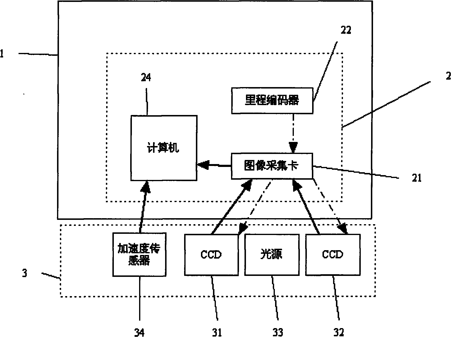
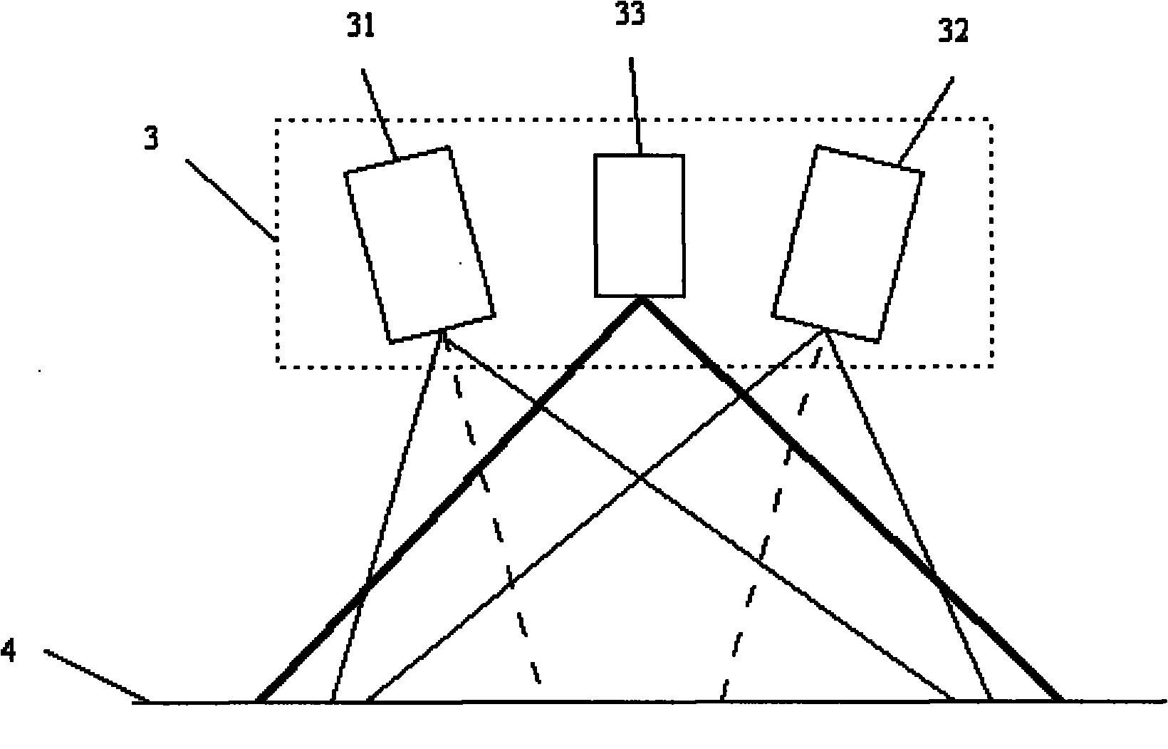
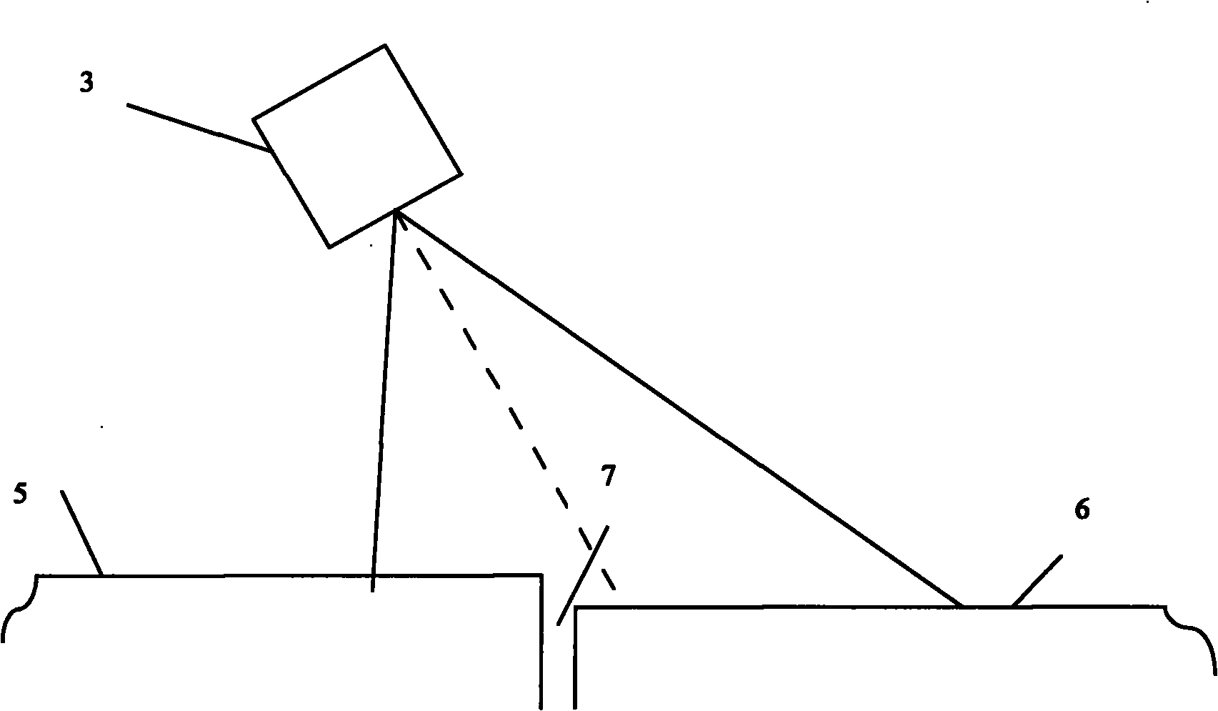
[0028] Example 1: Combining Figure 1-Figure 4 Illustrate the present embodiment, it is made of calculation processing system 2 and binocular vision detection assembly 3; Computer system is made of computer 24, image acquisition card 21 and mileage encoder 22; Image acquisition card 21 is installed on the PCI interface of computer, mileage The housing of encoder 22 is installed and fixed on the outside of the wheel of the detection vehicle, and the rotary shaft of encoder 22 is connected with the wheel, and keeps the same angular velocity with the wheel; the trigger signal line of encoder 22 is connected with the external trigger interface of image acquisition card 21; The binocular visual detection assembly 3 is made up of 2 surface array CCD image sensors 31, 32 and a surface light source 33. The lenses of the 2 surface array CCDs face the road, and their sampling areas overlap each other. The surface light source 33 covers the sampling area of ​​the CCD; the area array CCD ...

Embodiment 2

[0050] Embodiment two: the difference between this embodiment and embodiment one is that the CCD image sensors 31, 32 are two line scan cameras, the light source 33 is a line light source, the CCD image sensors 31, 32 and the line light source 33 face the road surface, and the CCD image sensor 31 and the scanning line of the CCD image sensor 32 are generally on the same straight line, and the irradiation line of the line light source 33 is also on this straight line, providing illumination for the two line scan cameras at the same time. Before the detection, the two line array cameras are calibrated, and an acceleration sensor and a gyroscope are installed in the binocular vision detection component 3 to record each scanning moment of the line scan camera, the vibration displacement of the two cameras, and when calculating the coordinates of the measuring point , to subtract the vibration displacement. Other compositions, connection methods and calculation methods are the same...


PUM


Abstract

The invention relates to a cement concrete pavement joint dislocation detection device and method based on binocular vision. The device comprises a calculation processing system and a binocular vision detection component, wherein an image acquisition card in the calculation processing system is connected with a computer to transmit the collected images, a mileage coder is arranged on the outside of the wheels of an inspection vehicle, the flip-flop signal wire of the mileage coder is connected with the image acquisition card; and the binocular vision detection component is arranged outside the vehicle body and comprises two CCDs of which sampling areas are overlapped and a light source shining on the sampling areas, and the CCDs are connected with the image acquisition card to ensure that the image acquisition card collects images and triggers the CCDs. The method of the invention comprises the following steps: 1) the mileage coder generates pulse signals, the image acquisition card triggers the CCDs to collect images of the same target; 2) positioning a joint of the pavement according to the images collected by the CCDs; and 3) selecting a plurality of measuring points on two concrete plates near the joint in the images collected by the CCDs, searching two corresponding images of each measuring point, and calculating joint dislocation quantity. The device and method of the invention can be used to accurately position dislocated joints.

Description

technical field [0001] The invention belongs to the field of road engineering, and relates to a detection device and a detection method for cement concrete pavement dislocation. Background technique [0002] Cement concrete pavement stagger refers to the difference in elevation between two adjacent cement slabs at the transverse joint in the cement concrete pavement. It is caused by a variety of reasons such as traffic load, temperature warping, and base layer scour. Staggering is an important factor affecting the flatness, life of cement concrete pavement and reflective cracks after overlaying. It is also an important index that must be considered in the evaluation of the technical condition of cement concrete pavement, maintenance and overlay design. Therefore, how to carry out accurate and efficient detection and evaluation of the wrong platform has become a problem of great concern to the highway management and maintenance department. [0003] The detection of wrong pl...

Claims


Application Information

Patent Timeline
Patent Type & Authority Applications(China)
IPC IPC(8): E01C23/01E01C11/04G01B11/02
Inventor 英红谈至明周玉民
Owner TONGJI UNIV
Why Eureka
Try Eureka