Cement concrete road surface dislocation detection device and method based on structured light vision

A technology of cement concrete and detection method, which is applied in the direction of roads, roads, pavement details, etc., can solve the problems of expensive, time-consuming and labor-intensive, and cannot accurately locate the wrong platform, and achieve the effect of reducing costs and reducing light source requirements

Inactive Publication Date: 2010-09-29
TONGJI UNIV
View PDF4 Cites 24 Cited by
  • Summary
  • Abstract
  • Description
  • Claims
  • Application Information

AI Technical Summary

Problems solved by technology

At present, the detection of the wrong platform in China is mainly realized by manual use of a ruler or a vernier caliper, which is time-consuming, laborious and unsafe
Some areas use laser profiler (ARRB system in Australia, PASI system of PAVEDEX company in the United States, South Dakota DOT system developed by the South Dakota Department of Transportation in the United States, automatic road inspection vehicle of ICC company in the United States, Australian NSW Highway Bureau and CRISO The automatic detection vehicle RoadCrack jointly developed by the company, the ARAN of RoadWare Company in Canada, the detection vehicle of WDW Company in the United Kingdom) or the ultrasonic profiler (ROMDAS ultrasonic road surface cross-section / rutting test system of DCL Company in New Zealand) can realize the measurement of the wrong platform, and the cross-section The instrument needs multiple distance sensors, usually 7 to 13, and some as many as 30, which is expensive; when using the profiler to detect the cement concrete pavement, it is impossible to accurately locate the wrong station

Method used


Image

  • Cement concrete road surface dislocation detection device and method based on structured light vision
  • Cement concrete road surface dislocation detection device and method based on structured light vision
  • Cement concrete road surface dislocation detection device and method based on structured light vision

Examples


Embodiment Construction

[0028] The present invention will be further described below with reference to the embodiments shown in the accompanying drawings.

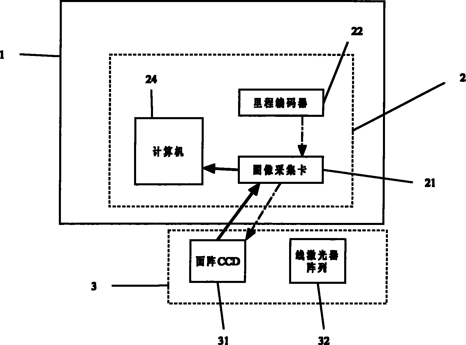
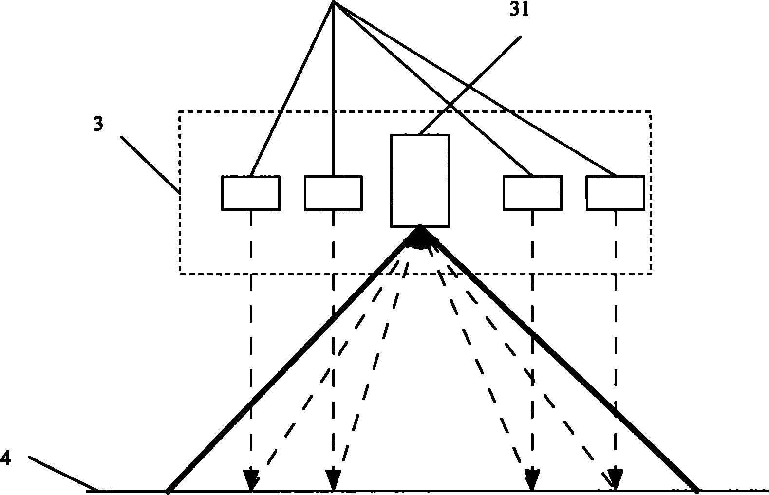
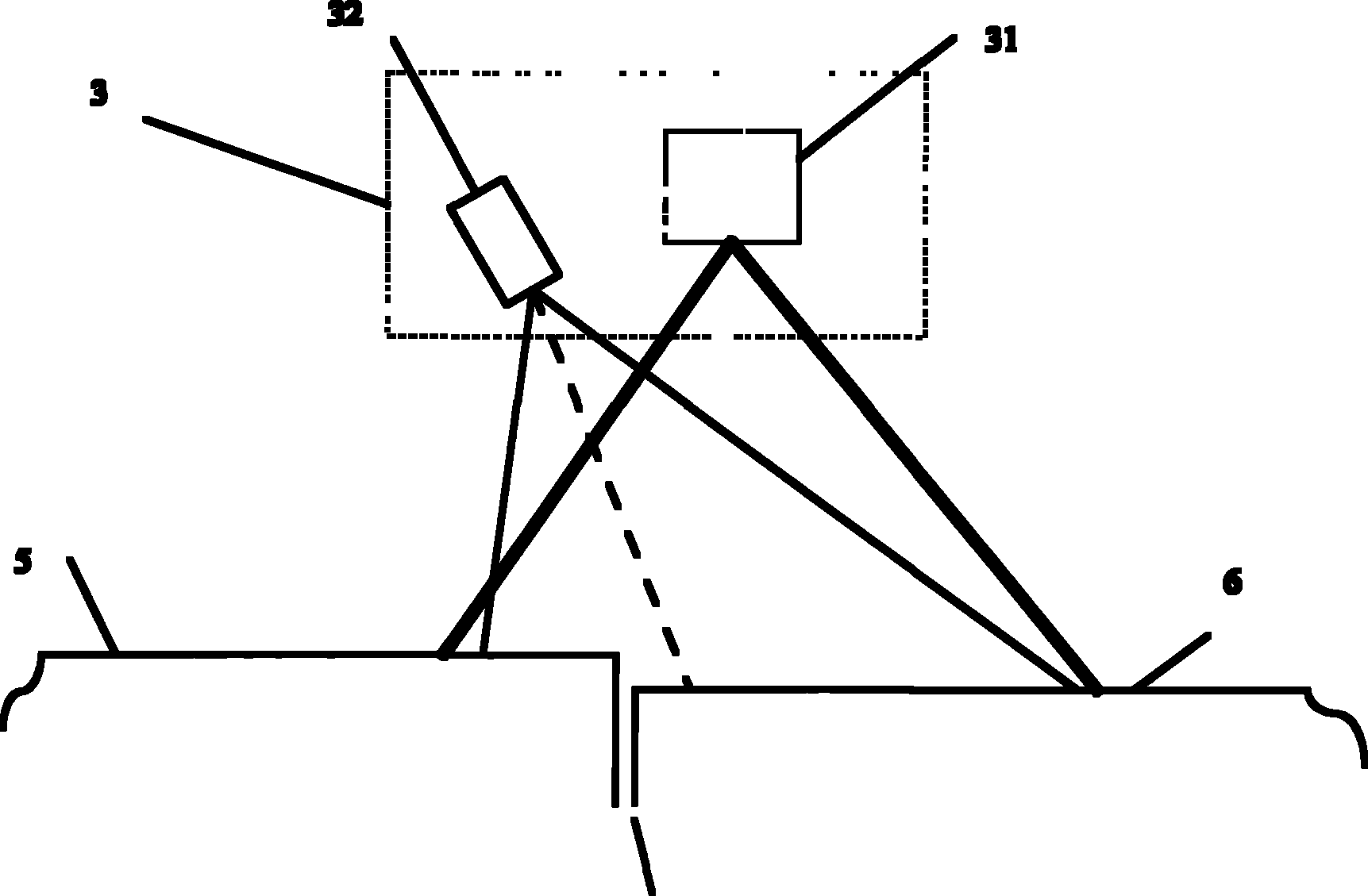
[0029] The road misalignment detection device of the present invention is composed of a computing processing system 2 and a structured light visual detection component 3; the computer system 2 is composed of a computer 24, an image capture card 21 and a mileage encoder 22; the image capture card 21 is installed on the PCI interface of the computer On the upper side, the casing of the mileage encoder 22 is installed and fixed on the outer side of the wheel of the detection vehicle, the rotating shaft of the encoder 22 is connected with the wheel, and maintains the same angular velocity as the wheel; the trigger signal line of the encoder 22 is connected to the external trigger of the image acquisition card 21 The structured light visual inspection component 3 is composed of a table array CCD image sensor 31 and a line laser array 32, the data line ...


PUM


Abstract

The invention relates to cement concrete road surface dislocation detection device and method based on structured light vision. The cement concrete road surface dislocation detection device comprises a computing system and a structured light vision detection component. An image acquisition card in the computing system is connected with a computer for sending acquired images; a trigger signal lineof a mileage encoder is connected with an external trigger interface of the image acquisition card; the structured light vision detection component is arranged at the bottom of the bodywork of a detection car and comprises a line laser array and an area array CCD (Charge Coupled Device) image sensor facing to the road surface; and a CCD is connected with the image acquisition card so that the image acquisition card acquires the images and triggers. The method comprises the following steps of: generating a pulse signal by the mileage encoder, triggering the CCD to acquire the road surface images comprising structured light bars by the image acquisition card, positioning seams of the road surface according to the acquired images, thinning the structured light bars in the acquired images, extracting the thinned structured light bars of two cement plates near the seams, and computing three-dimensional coordinates of pixels on the light bars to calculate the amount of dislocation. The invention can accurately position the dislocation.

Description

technical field [0001] The invention belongs to the field of road engineering, and relates to a cement concrete pavement misalignment detection device and a detection method. Background technique [0002] Cement concrete pavement staggering refers to the difference in elevation between two adjacent cement slabs at the transverse joints in the cement concrete pavement. It is caused by various reasons such as driving load, temperature warping, and base scouring. The staggered platform is an important indicator that affects the smoothness, service life and reflection cracks of cement concrete pavement. Therefore, how to accurately and efficiently detect and evaluate the wrong platform has always been a problem that the highway management and maintenance department is very concerned about. [0003] The detection of misplacement consists of two steps: one is to locate the joint, that is, to find the location of the misplaced platform; the other is to detect the elevation differ...

Claims


Application Information

Patent Timeline
IPC IPC(8): E01C23/01E01C11/04
Inventor 谈至明英红周玉民
Owner TONGJI UNIV
Why Eureka
Try Eureka