Damping device placed in reinforced concrete member

A technology of reinforced concrete and shock-absorbing device, which is applied to building components, earthquake-proof and other directions, can solve problems such as application obstacles, difficulties, and limited installation space, and achieve the effects of increasing the damping level, low engineering cost, and wide application range.

Inactive Publication Date: 2012-05-23
BEIJING UNIV OF TECH
View PDF0 Cites 1 Cited by
  • Summary
  • Abstract
  • Description
  • Claims
  • Application Information

AI Technical Summary

Problems solved by technology

There are the following defects in the installation of dampers inside the structure: first, the installation space of dampers inside many structures is limited by the requirements of architectural functions or aesthetics, and often there is not enough or suitable installation space; second, dampers generally require regular inspection and inspection. Maintenance, which increases the cost of using the damper; third, the nodes where the damper is installed need to be specially designed, which increases the design workload; fourth, the design and application of the damper requires specialized knowledge and technology, which has caused certain application obstacles; Fifth, the damping equipment of domestic large-scale projects mostly uses foreign dampers, and there are still certain difficulties in competing with similar domestic products
These factors have hindered the popularization and application of damping shock absorption technology in our country

Method used


Image

  • Damping device placed in reinforced concrete member
  • Damping device placed in reinforced concrete member
  • Damping device placed in reinforced concrete member

Examples


Embodiment 1

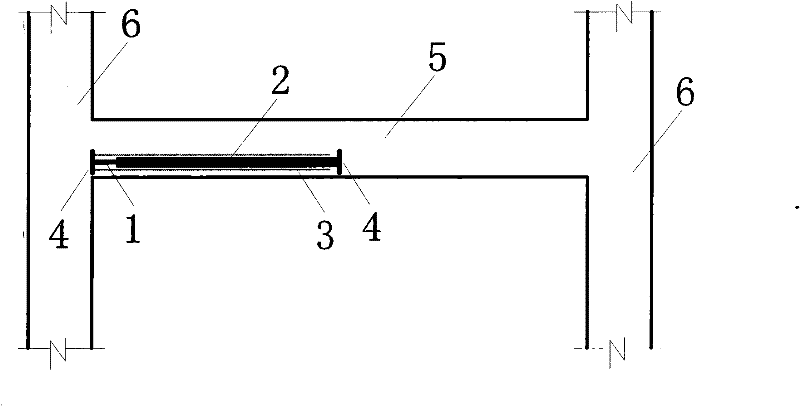
[0021] Such as figure 1 As shown, a damping anti-seismic device placed in a reinforced concrete member is placed on a frame beam, including a reinforced concrete beam 5, a damping steel bar 1, a connecting rod 2, a sleeve 3, and an anchoring component 4. (It is characterized in that:) the damping steel bar 1 is connected to the anchoring parts 4 at both ends through the connecting rod 2, the sleeve 3 sets the connecting rod 2 and the damping steel bar 1 in the tube, the damping steel bar 1, the connecting rod 2, the casing 3, and the anchor The components 4 together form an energy-dissipating fiber unit, and the energy-dissipating fiber unit is embedded in the reinforced concrete beam 5 . One of the two anchoring parts 4 is buried in the beam-column node area, and the other is buried in the midpoint of the beam, and plays an anchoring role in the concrete; the sleeve 3 separates the connecting rod 2 and the damping steel bar 1 from the concrete. Since the axial tensile stiffn...

Embodiment 2

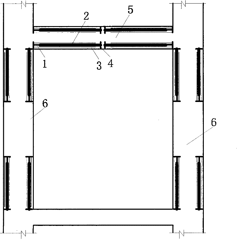
[0024] Such as figure 2 As shown, a damping and anti-seismic device placed in a reinforced concrete member is placed in a frame, including a frame beam 5, a frame column 6, a damping steel bar 1, a connecting rod 2, a casing 3, and an anchoring component 4. The damping steel bar 1 is connected to the anchoring parts 4 at both ends through the connecting rod 2, and the sleeve 3 covers the connecting rod 2 and the damping steel bar 1 in the tube. The energy-dissipating fiber unit is embedded in the reinforced concrete beam 5 and the reinforced concrete column 6, wherein the two anchor components 4 in the beam 5 are buried in the beam-column node area, and the other is buried in the beam midpoint The energy-dissipating fiber units in the column 6 are located at the upper and lower ends of the column 6 respectively. The anchoring part 4 plays an anchoring role in the concrete, and the casing 3 separates the connecting rod 2 and the damping steel bar 1 from the concrete. Since t...

Embodiment 3

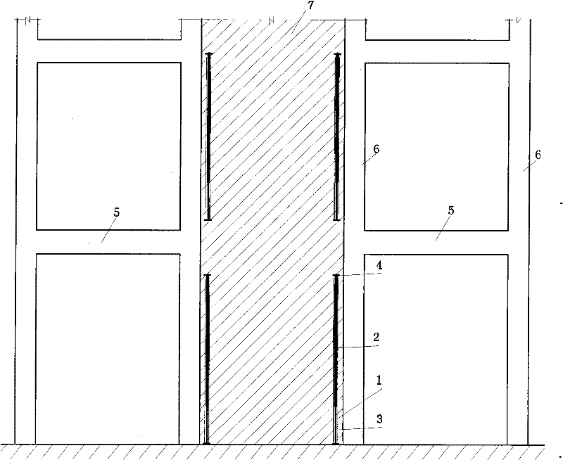
[0027] Such as image 3 As shown, a damping anti-seismic device placed in a reinforced concrete member is placed in a shear wall, including a shear wall 7, a damping steel bar 1, a connecting rod 2, a casing 3, and an anchoring component 4. (It is characterized in that:) the damping steel bar 1 is connected to the anchoring parts 4 at both ends through the connecting rod 2, the sleeve 3 sets the connecting rod 2 and the damping steel bar 1 in the tube, the damping steel bar 1, the connecting rod 2, the casing 3, and the anchor The components 4 together form an energy-dissipating fiber unit, which is embedded in the tension-compression area of ​​the reinforced concrete shear wall 7, and the energy-dissipating fiber units in the shear wall 7 are arranged continuously along both sides of the shear wall. The anchoring part 4 plays an anchoring role in the concrete, and the casing 3 separates the connecting rod 2 and the damping steel bar 1 from the concrete. Since the axial tensi...


PUM


Abstract

The invention relates to a damping device placed in a reinforced concrete member. The damping device comprises a damping reinforcing steel bar, a connecting rod, an anchoring part and a sleeve, wherein one end of the damping reinforcing steel bar is connected with the anchoring part, while the other end is connected with the connecting rod; the other end of the connecting rod which is connected with the damping reinforcing steel bar is connected with the anchoring part; and a connecting rod 2 and a damping reinforcing steel bar 1 are sleeved into the sleeve by a sleeve 3. The damping device is embedded into a longitudinal fiber tensioning and compressing deformation region of the reinforced concrete member and the axially tensile rigidity of the connecting rod is far more than that of thedamping reinforcing steel bar, so the relative displacement of the anchoring part at the two ends is converted into the deformation concentrated to the damping reinforcing steel bar and the damping reinforcing steel bar enters a surrendering state earlier than the reinforcing bar of the reinforced concrete member. The damping level of the reinforced concrete member is enhanced through larger plastic strain energy consumption, so that damping protection is provided for the reinforced concrete member.

Description

technical field [0001] The invention relates to damping and shock absorption control of building structures, in particular to a damping and shock resistance device placed in reinforced concrete components. Background technique [0002] In recent years, there have been many earthquakes with great destructive power in my country. Among them, the Wenchuan earthquake and Yushu earthquake caused the loss of life and property, and the whole country mourns for it. Most of my country's cities and important industrial buildings are located in earthquake zones, and earthquake hazards will threaten us for a long time. Therefore, it has important economic value and social significance to reduce the destructive loss of building structures in earthquake action. [0003] The current commonly used shock absorption technology is mainly through the installation of dampers inside the building. The inter-story displacement of the building is used to drive the damper to work, increasing the st...

Claims


Application Information

Patent Timeline
Patent Type & Authority Patents(China)
IPC IPC(8): E04B1/98
Inventor 彭凌云周锡元闫维明
Owner BEIJING UNIV OF TECH
Why Eureka
Try Eureka