Card inserting and elastic retreating mechanism

A technology of inserting cards and inserting card slots, which is applied in the field of ejection mechanisms for inserting card-type networked computers, which can solve problems such as complex ejection mechanism structures and ejection failures, and achieve the effects of simple structure, convenient replacement, and reduced equipment volume

Active Publication Date: 2021-12-31
炜呈智能电力科技(杭州)有限公司
View PDF3 Cites 0 Cited by
  • Summary
  • Abstract
  • Description
  • Claims
  • Application Information

AI Technical Summary

Problems solved by technology

The structure of the current exit mechanism is complex, and it is prone to exit failures and other phenomena

Method used


Image

  • Card inserting and elastic retreating mechanism
  • Card inserting and elastic retreating mechanism
  • Card inserting and elastic retreating mechanism

Examples


Embodiment 1

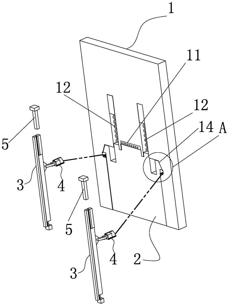
[0043] Such as figure 1 As shown, a card ejection mechanism in this embodiment includes a card socket 1 , an elastic buckle slot 14 , a card 2 , an elastic buckle 21 and a locking control system.

[0044] The card socket 1 is generally arranged on the host, and the card socket 1 has a card slot 11. Meanwhile, both the card socket 1 and the card 2 are block-shaped to further improve the compactness of the structure.

[0045] The card 2 is inserted into the card slot 11 from the notch of the card slot 11 .

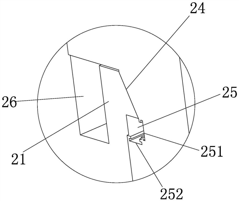
[0046] There are two elastic buckle slots 14 and they are arranged on opposite sides of the slot walls of the card insertion slot 11 .

[0047] When the card 2 is inserted into the card slot 11, the two elastic buckles 21 are respectively in contact with the opposite sides of the card slot 11 and deformed inwardly, and when the card 2 is inserted into the card slot 11, the elastic buckles 21 are in place. The buckle 21 recovers and deforms outward so that the elastic buckl...

Embodiment 2

[0066] The other structure of this embodiment is the same as that of Embodiment 1, except that an elastic reset assembly is provided on the buckle pad linkage mechanism 3, which drives the buckle pad 4 to reset in the axial linear displacement of the elastic buckle groove 14, so that the elastic buckle 21 is buckled on the horizontal contact surface 42 of the buckle pad 4 again. Such as Figure 6 and Figure 7 As shown, the elastic return assembly includes a plurality of return springs 8 parallel to each other, one end of the return spring 8 is connected to the fixed block 7 fixed on the slide rail 31, and the other end of the return spring 8 is connected to the buckle pad 4. One end of the horizontal contact surface 42 , and the return spring 8 is perpendicular to the buckle pad 4 is provided with one end of the horizontal contact surface 42 . The return spring 8 has the effect of helping the buckle pad 4 to reset. Because for the empty card socket 1, it is necessary to en...

Embodiment 3

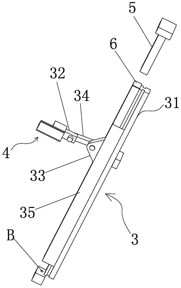
[0067] The working principle and structure of this embodiment are basically the same as that of Embodiment 1, and the different structures are: as figure 2 As shown, the end of the slider 35 without the magnet 6 is fixed on the chassis, and there is a certain distance from the chassis, where a jack B is arranged on the chassis. When encountering an emergency and needing to forcibly eject the card 2, you can use an extra thimble or other tools to touch the slider 35 through the chassis jack B, and push the slider 35 to slide, which can produce the same ejection effect. After ejecting, remove the thimble, and it can be restored.

[0068] The thimble of this embodiment is equivalent to another manual driving mode replacing the magnetic driving assembly.


PUM


Abstract

The invention belongs to the field of computer hardware, and particularly discloses a card inserting and elastic retreating mechanism, which comprises a card inserting base with a card inserting slot; two elastic buckling grooves formed in the groove walls of the two opposite sides of the card inserting groove; a plug-in card inserted into the card inserting slots from notches of the card inserting slots; two elastic buckles, wherein the elastic buckles are arranged on the plug-in card, when the plug-in card is inserted into the card inserting slots, the two elastic buckles are in contact with the slot walls of the two opposite sides of the card inserting slots respectively and deform inwards oppositely, and when the plug-in card is inserted into the card inserting slots in place, the elastic buckles recover deformation outwards, so that the elastic buckles extend into the corresponding elastic buckling grooves; and a locking control system which is used for enabling the elastic buckles to be axially locked in the elastic buckling grooves after the plug-in card is inserted into the card inserting slots in place, and cancelling the axial locking of the elastic buckles in the elastic buckling grooves. The card inserting and elastic retreating mechanism has the advantages of being simple in structure and convenient to operate.

Description

technical field [0001] The invention belongs to the field of computer hardware, and in particular relates to a pop-up mechanism for a card-type networked computer. Background technique [0002] Plug-in network computers are mainly used in environments that require multiple computers for combined communication. It is mainly composed of a host computer and different card machines. The card machine has the function of network communication, can be inserted into the card slot, and can start automatically when it is powered on. After obtaining the IP, the card machine can broadcast a message, get the response from other card machines, and connect to the network with other card machines. Before being pulled out, the card machine sends a broadcast message to obtain responses from other card machines, and when the pulling-out condition is met, it sends a signal to the withdrawal mechanism, and the withdrawal mechanism withdraws from the card slot. The structure of the exit mechan...

Claims


Application Information

Patent Timeline
Patent Type & Authority Applications(China)
IPC IPC(8): H04B1/3818
CPCH04B1/3818
Inventor 龚勇张明轩张宏锦
Owner 炜呈智能电力科技(杭州)有限公司
Why Eureka
Try Eureka