
Electro-hydraulic actuator of hydraulic integration machine

A hydraulic integration, electromechanical hydraulic technology, applied in the direction of mechanical equipment, fluid pressure actuation devices, fluid pressure actuation system components, etc., can solve problems such as valve opening and closing, unstable pressure, oil leakage at high pressure points, etc. To achieve the effect of reduced size, complete functions and quick response

Inactive Publication Date: 2010-09-29
LISHUI ZHONGDE PETROCHEM EQUIP
View PDF5 Cites 6 Cited by
  • Summary
  • Abstract
  • Description
  • Claims
  • Application Information

AI Technical Summary

Benefits of technology

This new type of electric or pneumatic powered device uses an electrical signal instead of water pressure for controlling its movement. Unlike previous designs that had multiple large components like springs, this design allows for precise positional changes without requiring significant maintenance over time. Its technical effect is improved efficiency compared to existing systems while reducing space requirements by saving material and making it lighterweight than older methods such as spring mechanisms.

Problems solved by technology

This patented technical problem addressed in this patents relates to traditional hydrauled integrated electric machine (EML) hydrauike actuator designs that have issues related to their size and potential leaks during operation due to direct connection between them without proper sealing measures.

Method used


Image

  • Electro-hydraulic actuator of hydraulic integration machine
  • Electro-hydraulic actuator of hydraulic integration machine
  • Electro-hydraulic actuator of hydraulic integration machine

Examples


Embodiment Construction

[0016] In conjunction with the accompanying drawings, the present invention will be specifically described below through the embodiments. The same parts are denoted by the same reference numerals in the drawings. It must be pointed out that this embodiment is only used to further illustrate the invention, but should not be construed as limiting the protection scope of the invention. Those skilled in the art can make some non-essential improvements and adjustments to the present invention based on the technical content provided above.

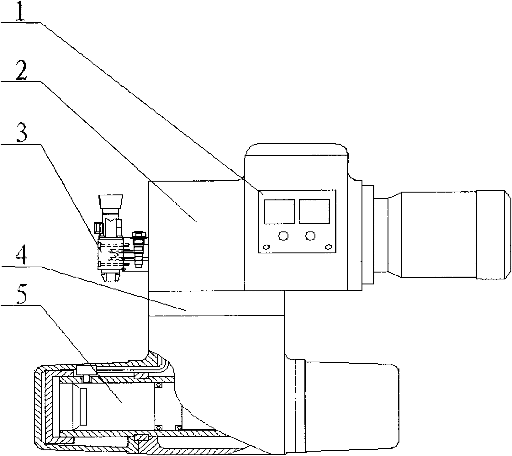
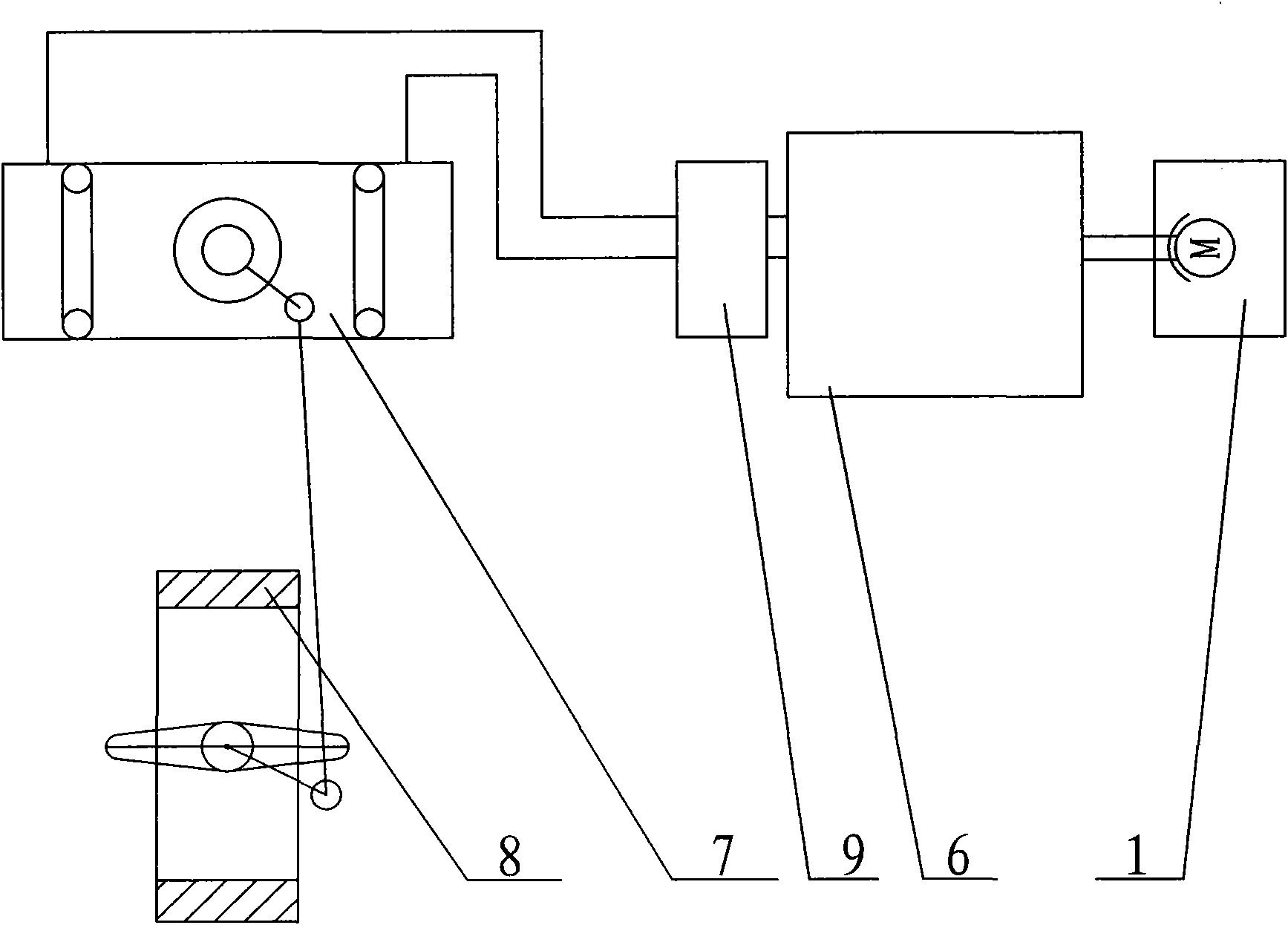
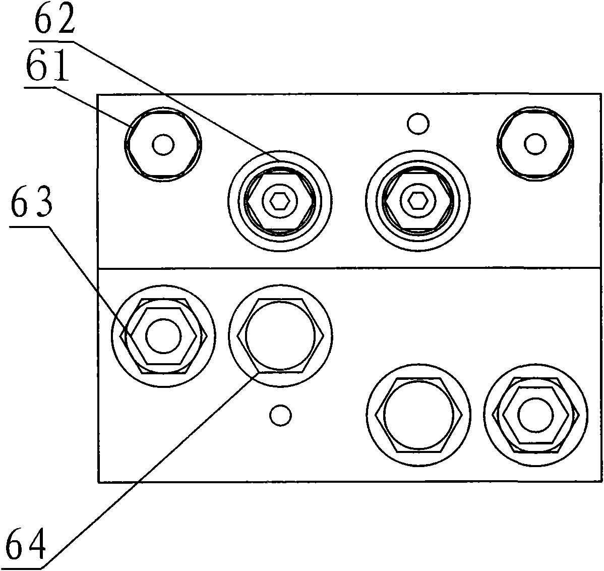
[0017] A hydraulically integrated electro-hydraulic actuator, including an electric control system 1, a hydraulic system 2, a hand-operated mechanism 3, an oil tank 4, and an oil cylinder 5, wherein the electric control system 1 is connected to the hydraulic system 2, and the hydraulic system 2 is connected to the hand-operated mechanism 3 respectively , the oil tank 4 is connected, the oil tank 4 is connected with the oil cylinder 5; the hydra...


PUM


Abstract

The invention provides an electro-hydraulic actuator of a hydraulic integration machine, which comprises an electric control system, a hydraulic system, a hand operation mechanism, an oil tank and an oil cylinder, wherein the electric control system is connected with the hydraulic system, the hydraulic system is respectively connected with the hand operation mechanism and the oil tank, and the oil tank is connected with the oil cylinder. The invention is characterized in that the hydraulic system comprises an oil path and a hydraulic integration block, wherein one end of the hydraulic integration block is connected with the electric control system, the other end of the hydraulic integration block is connected with the hydraulic cylinder through a gear two-way pump, and the hydraulic cylinder is connected with a disc valve. Compared with the prior art, the electro-hydraulic actuator of the hydraulic integration machine of the invention can realize the regulation and the cut-off control of the valve, the huge hydraulic station of the hydraulic control system is omitted, the size is greatly reduced, the materials are saved, and the investment is reduced. The invention has the advantages of complete function, compact structure, small size, light weight, fast response and the like.

Description


Claims


Application Information

Patent Timeline
Owner LISHUI ZHONGDE PETROCHEM EQUIP
Learn More