Single-phase earth fault location system for distribution network of power system and method thereof

A single-phase grounding fault and locating system technology, applied in fault location, information technology support system, measurement using digital measurement technology, etc. Low cost and great practicality

Active Publication Date: 2010-09-29
ELECTRIC POWER RESEARCH INSTITUTE OF STATE GRID SHANDONG ELECTRIC POWER COMPANY +1
View PDF6 Cites 32 Cited by
  • Summary
  • Abstract
  • Description
  • Claims
  • Application Information

AI Technical Summary

Problems solved by technology

[0018] Aiming at the problem of difficult location of single-phase ground fault in distribution network, the present invention proposes a brand-new single-phase ground fault location system and method of power system distribution network

Method used


Image

  • Single-phase earth fault location system for distribution network of power system and method thereof
  • Single-phase earth fault location system for distribution network of power system and method thereof
  • Single-phase earth fault location system for distribution network of power system and method thereof

Examples


Embodiment 1

[0059] The system consists of the following three parts:

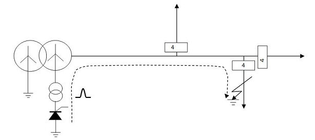
[0060] 1) Thyristor-based pulse signal generator 1. The thyristor-based pulse signal generator 1 is mainly composed of a pair of thyristors connected in antiparallel. This part is placed between the neutral point of the main transformer 2 of the substation and the earth, such as figure 1 shown. When a single-phase ground fault occurs in the distribution network of the power system, the thyristors installed at the two positions in the figure will conduct instantaneously between the neutral point of the control system and the earth, so as to generate a relatively large short-circuit current and inject it into the power system.

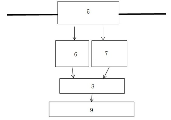
[0061] 2) Current sensor 4. The current sensor 4 is installed at the initial end of each outlet bifurcation branch, such as image 3 shown. The current sensor 4 is integrated on each phase conductor, self-powered, such as Figure 4 shown. It consists of the following parts:

[0062] (a) ...

Embodiment 2

[0076] In this embodiment, the pulse signal generator 1 is installed on the Y connected to the busbar 0 In the Δ winding of the / Δ-type transformer 3, other structures are the same as those in Embodiment 1, and will not be repeated here.

[0077] Operating procedure of the present invention is as follows:

[0078] 1) Detect the occurrence of ground fault. Whether a single-phase ground fault occurs in the system can be found by detecting the bus voltage of the substation.

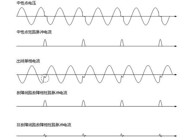
[0079] 2) The signal generator starts to work. By controlling the firing angle of the thyristor to generate a short-circuit current with a specific cycle, for example, 15 seconds per cycle, and a sufficient intensity to flow into the system.

[0080] 3) The continuously working sensor detects the short-circuit current signal. If a current sensor detects a short-circuit current signal, it transmits its status value "1" and its own ID number to the master station. Only sensors with a status value of "1" s...


PUM


Abstract

The invention relates to a single-phase earth fault location system for a distribution network of a power system and a method thereof. The single-phase earth fault location system comprises a pulse signal generator, which is arranged between the neutral point of a main substation transformer and the ground, and the initial end of each outlet branch is provided with a current sensor; and a main station is also mounted in a substation, and is communicated with the current sensors. The method installs the thyristor-based short-circuit current generator at a corresponding position in the substation, thyristors are controlled to instantaneously conduct in order to generate and inject short-circuit current into a faulty line, the sensors mounted on the initial ends of the outlet branches detectthe short-circuit current, each sensor detecting the short-circuit current informs a host positioned in the substation of own state information via communication, and according to calculated fault impedance coupled with the locations of the sensors detecting the short-circuit current, the host determines the location where a single-phase earth fault occurs.

Description

Technical field [0001] The present invention involves a power system fault positioning system and method of power system distribution grid. Background technique [0002] The power supply interruption of the power system will lead to the production of power outages, chaos, and even crisis of personal safety. Ensuring safety and reliability power supply is the basic requirement for the operation of the power system.With the development of the economy and the improvement of people's living standards, users have put forward higher requirements for power supply reliability and security.With the further opening of the power market, the quality of power supply will be more stringent constraints and supervision, which will be directly linked to the economic benefits and operational qualifications of the power sector.Both power users and power supply companies have their own needs to improve power supply reliability.The main factor affecting the reliability of power supply is the power ou...

Claims


Application Information

Patent Timeline
Patent Type & Authority Applications(China)
IPC IPC(8): G01R31/08G01R19/25
CPCY04S10/522Y04S10/52
Inventor 贾善杰朱珂
Owner ELECTRIC POWER RESEARCH INSTITUTE OF STATE GRID SHANDONG ELECTRIC POWER COMPANY
Why Eureka
Try Eureka