
Colorful filter array substrate

A color filter array and color filter layer technology, applied in optics, nonlinear optics, instruments, etc., can solve problems such as multiple alignment errors, increased production costs, and complex structures

Inactive Publication Date: 2010-09-29
华映视讯(吴江)有限公司 +1
View PDF0 Cites 2 Cited by
  • Summary
  • Abstract
  • Description
  • Claims
  • Application Information

AI Technical Summary

Problems solved by technology

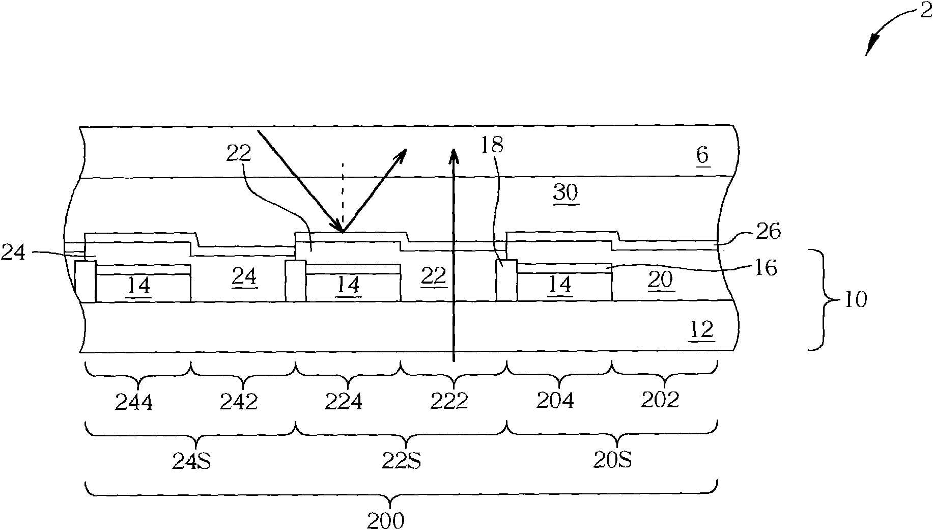
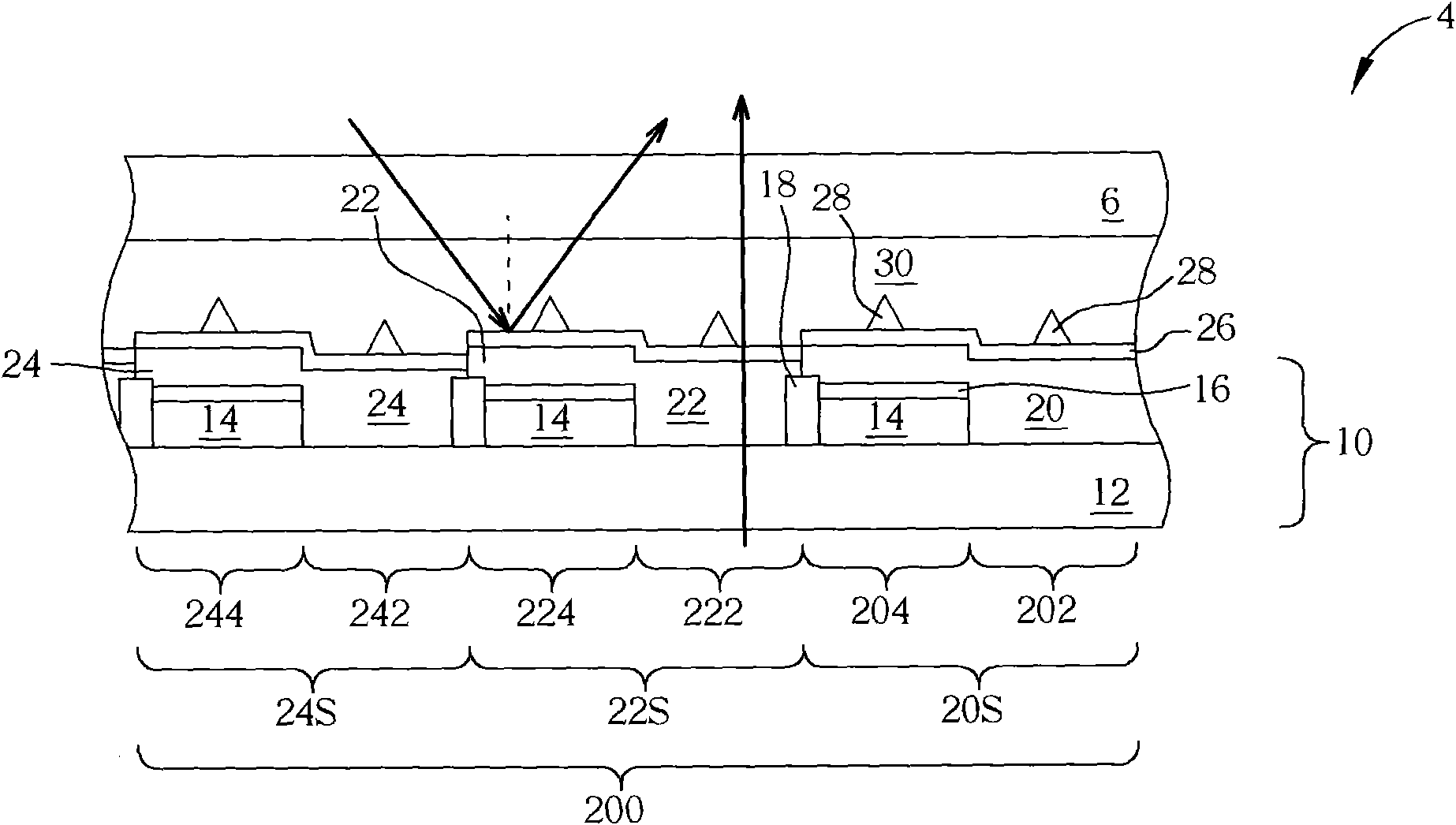
[0006] However, the known liquid crystal displays that combine wide viewing angle technology and transflective technology all add a plurality of bumps in the transmissive area and reflective area of ​​the color filter array substrate, so that it is necessary to add a lithography and Etching (photo-etching process, PEP) process steps, not only has a complex structure, increases production costs, but also relatively increases alignment errors

Method used


Image

  • Colorful filter array substrate
  • Colorful filter array substrate
  • Colorful filter array substrate

Examples


Embodiment Construction

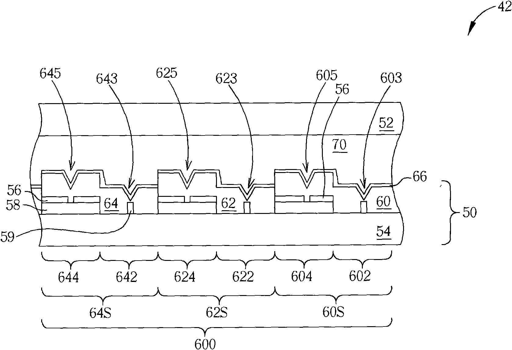
[0044] Please refer to image 3 , image 3It is a schematic diagram of the first embodiment of the color filter array substrate 50 according to the present invention. image 3 As shown, the color filter array substrate 50 of this embodiment is applied in a semi-transmissive and semi-reflective wide viewing angle liquid crystal display 42, and together with another transparent upper substrate 52 and a liquid crystal layer 70 constitute the transflective and semi-reflective Type wide viewing angle liquid crystal display 42. The color filter array substrate 50 includes a transparent substrate 54 , and a plurality of pixels 600 are disposed on the transparent substrate 54 and located between the transparent upper substrate 52 and the transparent substrate 54 . To simplify the description, only one pixel 600 is taken as an example, wherein each pixel 600 may include a plurality of sub-pixels 60S, 62S, 64S, respectively provided with color filter layers of different colors, such a...


PUM


Abstract

The invention provides a colorful filter array substrate applied to a semi-penetration and semi-reflection type wide-view angle LCD, comprising a transparent substrate and a plurality of sub-pixels, wherein each of the sub-pixels respectively comprises a reflecting region, a penetrating region, a colorful filter layer with at least one groove, and a transparent pole. The invention realizes a wide-view angle technology of a semi-penetration and semi-reflection type LCD by utilizing the groove on the colorful filter layer so as to simplify the structure, shorten the manufacturing process and effectively improve the production capacity of liquid crystal display panels.

Description

technical field [0001] The invention provides a color filter array substrate, especially a color filter array substrate used for a transflective and semi-reflective liquid crystal display with a wide viewing angle. Background technique [0002] According to different sources of illumination light, liquid crystal displays can be divided into three types: transmissive mode, reflective mode, and transflective mode. The transmissive liquid crystal display has a backlight for generating light, and the light generated by the backlight passes through the liquid crystal display panel to allow users to watch the display screen of the liquid crystal display. The reflective liquid crystal display is provided with a reflective layer. When the reflective liquid crystal display displays a picture, the ambient light enters the liquid crystal display from the user's viewing surface, and then reflects the light through the reflective layer of the liquid crystal display panel, and the reflect...

Claims


Application Information

Patent Timeline
IPC IPC(8): G02F1/1335
Inventor 王尹
Owner 华映视讯(吴江)有限公司
Learn More