Rolling bearing having internal lubrication

A kind of rolling bearing and bearing technology, which is applied in the field of rolling bearing of rolling parts, can solve the problem of not allowing the lubrication of rolling parts in an effective and economical way.

Inactive Publication Date: 2010-09-29
AB SKF
View PDF5 Cites 13 Cited by
  • Summary
  • Abstract
  • Description
  • Claims
  • Application Information

AI Technical Summary

Problems solved by technology

None of these known structures allow satisfactory lubrication of the rolling parts in a really efficient and economical way

Method used


Image

  • Rolling bearing having internal lubrication
  • Rolling bearing having internal lubrication
  • Rolling bearing having internal lubrication

Examples


Embodiment Construction

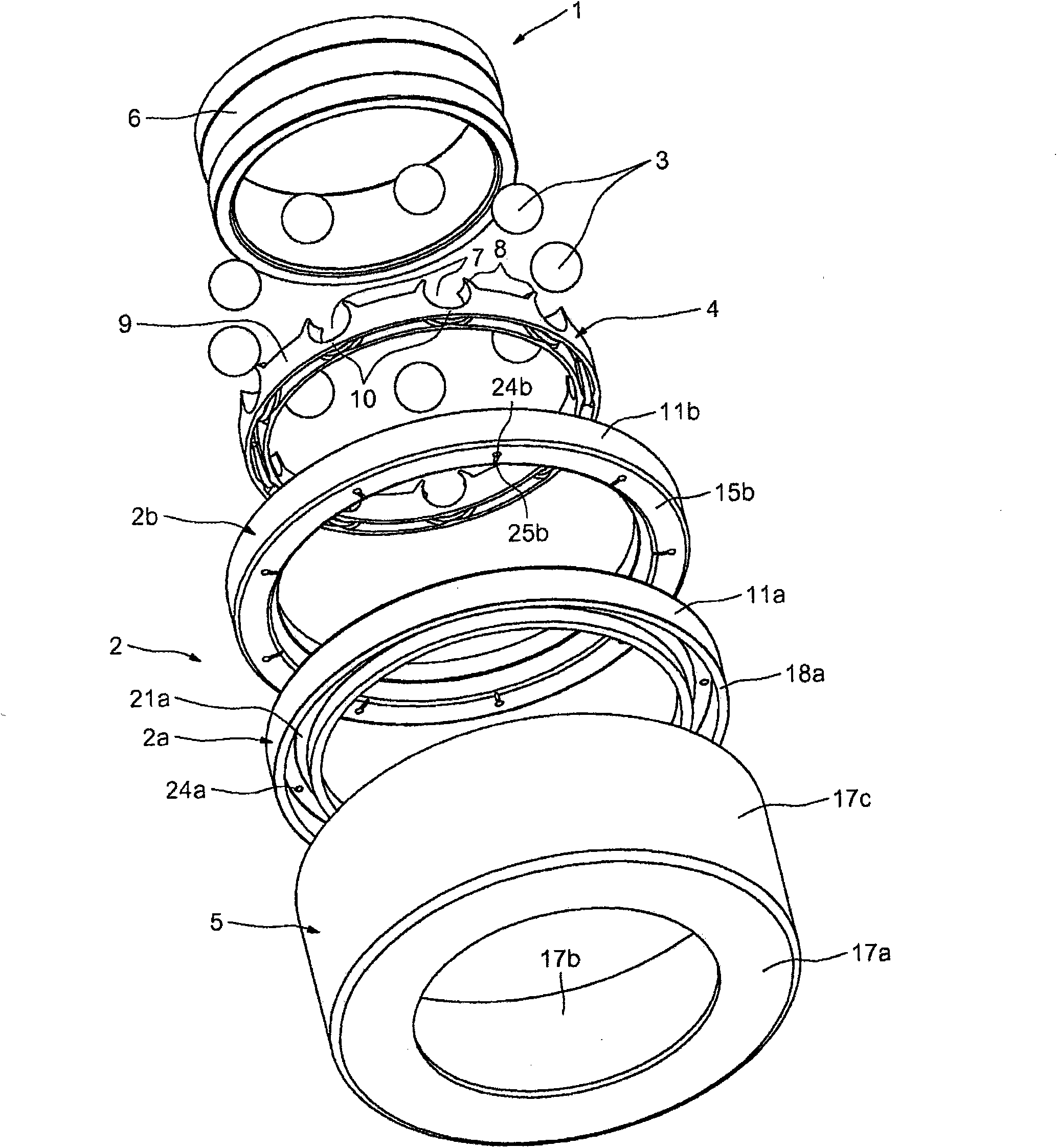
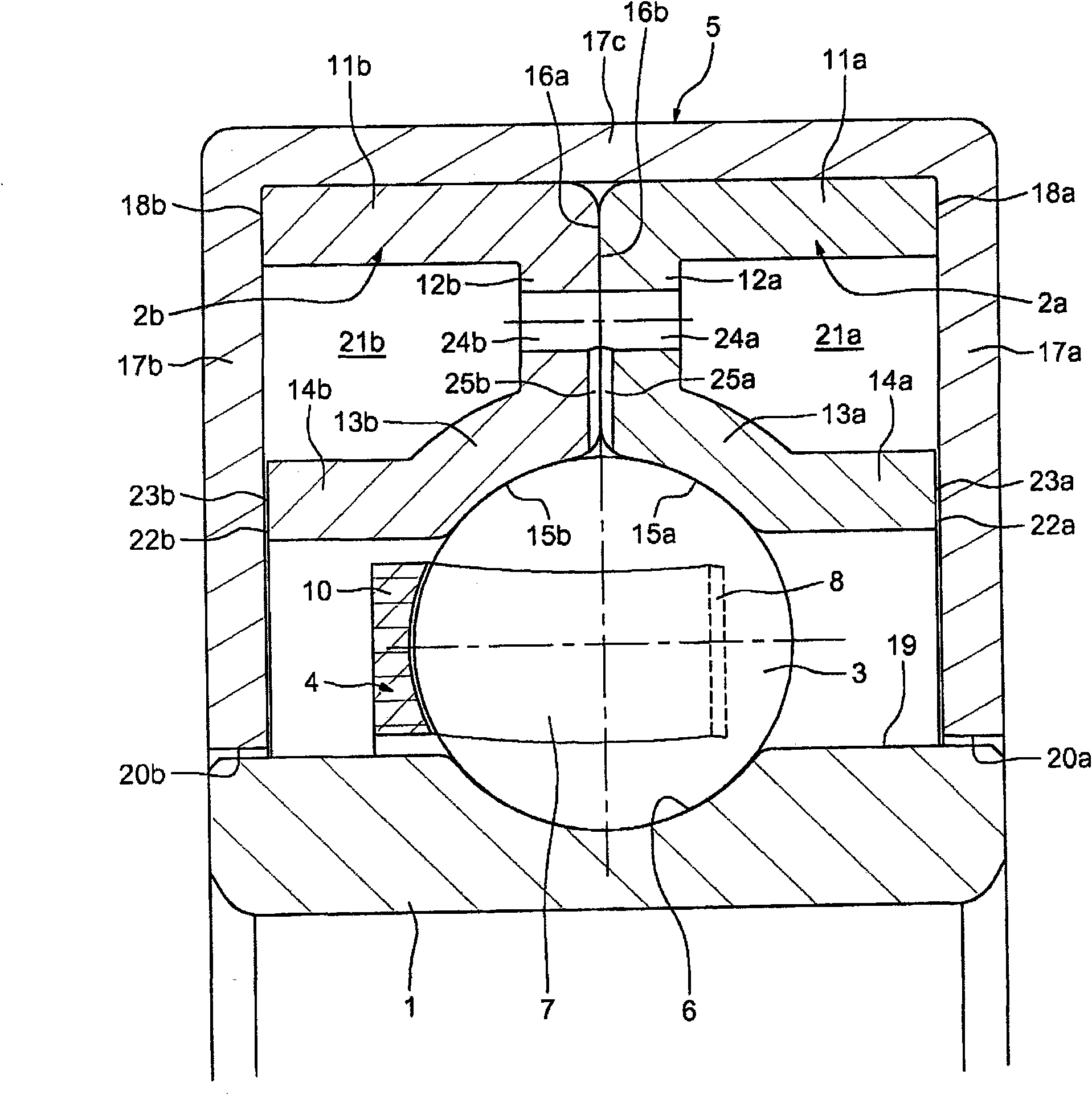
[0038] First refer to figure 1 and 2 , which shows a first embodiment of a rolling bearing according to the invention, said bearing having an inner ring 1 and an outer ring 2 and a row of rolling parts, said outer ring consisting of two outer half rings 2a, 2b, said rolling The components consist in the example shown of balls 3 held between inner ring 1 and outer ring 2 by cage 4 . An annular housing 5 surrounds the two outer half-rings 2a, 2b.

[0039] In this example, the inner ring 1 is designed to be mounted in a rotating part. In this way, the inner ring 1 constitutes the rotating ring of the bearing, while the outer ring 2 constitutes the non-rotating ring. The inner ring 1 is solid and has an annular groove 6 with a radius of curvature slightly greater than that of the balls 3 and forming a bearing raceway for the balls 3 . The inner ring 1 can be given its geometry and its final surface finish by turning or by forming a billet, then grinding and optionally polishin...


PUM


Abstract

Rolling bearing having an inner ring (1) and an outer ring (2) with a row of rolling elements (3) held by a cage (4) between bearing races provided on the two rings, and an annular housing (5) surrounding one of said rings. Said ring forms with the housing at least one closed space (21a), (21b), inside which a lubricant is located.

Description

technical field [0001] The invention relates to rolling bearings, in particular rolling bearings having an inner ring and an outer ring and one or more rows of rolling elements held by cages between bearing raceways provided on the two rings. The rolling elements can be balls, for example. The rolling bearings may be, for example, rolling bearings used in industrial electric motors or motor vehicle gearboxes. In such applications, the bearings are primarily radially loaded, usually with relatively small loads compared to the capabilities of the bearings used. The rotational speed in such an application is of the order of 3000 rpm. In such applications, the service life of rolling bearings is essentially related to the lubrication of the bearings. Any defect in a lubricated bearing usually leads to rapid degradation and failure of the bearing. Background technique [0002] Traditionally, deep groove rolling bearings with a single row of balls have seals or sealing flanges...

Claims


Application Information

Patent Timeline
Patent Type & Authority Applications(China)
IPC IPC(8): F16C19/16F16C33/60F16C33/66
CPCF16C19/163F16C33/767F16C33/60F16C19/06F16C33/6614F16C33/588F16C33/6648F16C33/6674F16C2361/61F16C2380/26
Inventor 让-卢克·加德勒亚历山大·曼塞厄伊薇斯-安德烈·利夫雷托
Owner AB SKF
Why Eureka
Try Eureka