Freeze and shock proof turnout
A technology of turnouts and turnouts, applied in the field of turnout devices, which can solve the problems of turnout function failure, improper switch rail movement, and energy consumption, and achieve the effects of reducing shock vibration and noise, increasing turnout life, and eliminating harmful spaces
- Summary
- Abstract
- Description
- Claims
- Application Information
AI Technical Summary
Problems solved by technology
Method used
Image

Examples
Embodiment 1
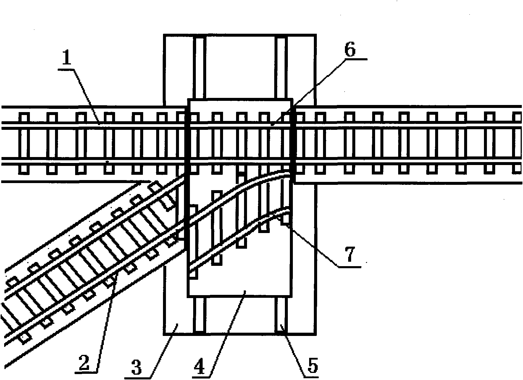
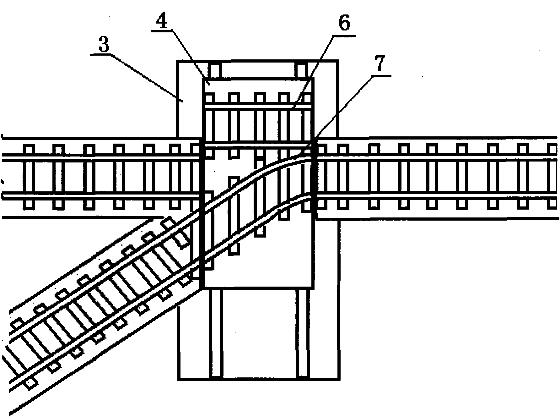
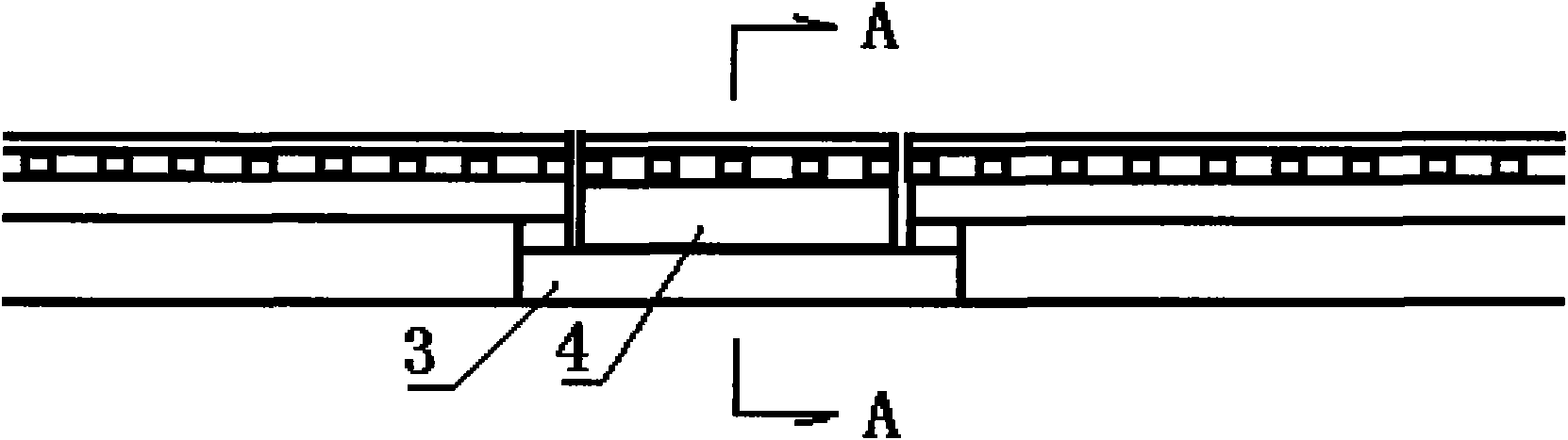
[0029] figure 1 As shown in , the base 3 on one side of the ram 4 is provided with a straight rail, and the other side is provided with a straight rail 1 and a branch rail 2; Transition rail 7; Motor 8 and screw 9 of ram driving device are provided in ram inner space (see diagram 2-1 ), one end of the screw is located in the screw thread fixedly arranged in the boss 10 on the base, the other end of the screw is connected to the motor shaft or the motor reduction device, and the driving device is controlled by a travel switch or a pressure sensor arranged on the ram or the boss to reciprocate journey.
[0030] image 3 As shown in , the two ends of the straight transition rail 6 and the branch transition rail 7 arranged side by side on the ram are fixedly installed on the ram, and at the same time, there are seamless joints 11 in the straight transition rail and the branch transition rail, eliminating the need for weather and seasonal changes. Thermal expansion and contract...
Embodiment 2
[0038] Figure 5 As shown, a positioning device is provided between the ram 3 and the base 4. The positioning device is composed of a positioning sleeve 13, a positioning sliding shaft 14, a sliding shaft sleeve 15 and a driving device. At the same time, the positioning sleeve or the sliding shaft located in the positioning sleeve 14 The outer end is provided with a travel switch or a pressure sensor to control the operation of the sliding shaft. In the sliding shaft sleeve or at the inner end of the sliding shaft in the sliding shaft sleeve, a travel switch or a pressure sensor is set to control the reset stroke of the sliding shaft; in the sliding shaft sleeve 15 or at the inner end of the sliding shaft in the sliding shaft sleeve, there is also a Pressure sensor that controls the ram drive.
[0039] In the application, when it is necessary to change the traffic state of the turnout, the power supply of the driving device in the positioning device is first turned on in reve...
PUM
 Abstract
Description
Claims
Application Information
PatSnap Eureka turns technology decisions into work you can execute. Powered by our Innovation Knowledge Graph, it runs expert workflows across engineering, life sciences, materials and intellectual property. Get your review-ready output in minutes.


