Floor block connecting structure and floor block adopting the same

A technology for connecting structures and floor plates, applied in building structures, floors, buildings, etc., can solve problems such as the difficulty of ensuring the strength of the slot or tongue, affecting the aesthetic effect of splicing, and difficult splicing structures, etc. Achieve the effect of improving assembly accuracy and connection strength, strong aesthetics and good connection strength

Inactive Publication Date: 2010-10-06
BEI JING NEW BUILDING MATERIALGRP
View PDF0 Cites 5 Cited by
  • Summary
  • Abstract
  • Description
  • Claims
  • Application Information

AI Technical Summary

Problems solved by technology

However, since the Ozon board itself is pressed by multi-layer shavings, the density of the board is low, and the milled slots or tongues are difficult to meet the strength requirements, so it is not easy to form a stable and reliable splicing when assembling structure, which is prone to surface unevenness, which affects the aesthetic effect of splicing
In addition, because this connector assembly method has been used for too long, the parts of the connector are easy to loosen, which will also affect the connection effect

Method used


Image

  • Floor block connecting structure and floor block adopting the same
  • Floor block connecting structure and floor block adopting the same
  • Floor block connecting structure and floor block adopting the same

Examples


Embodiment Construction

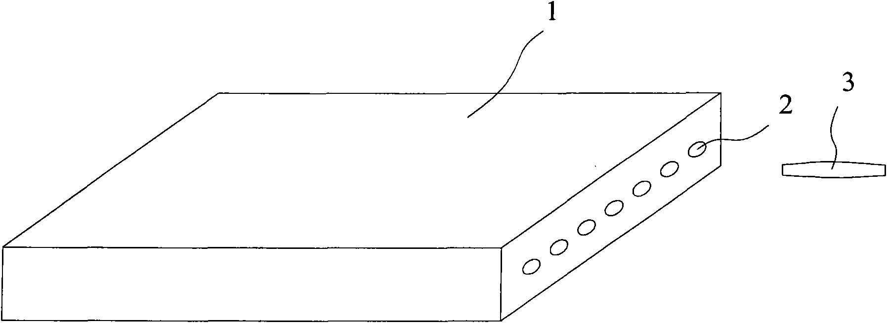
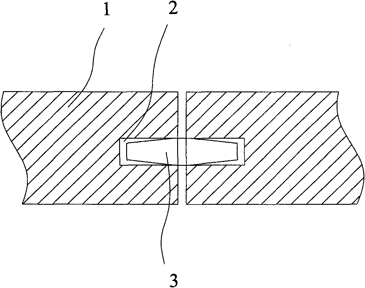
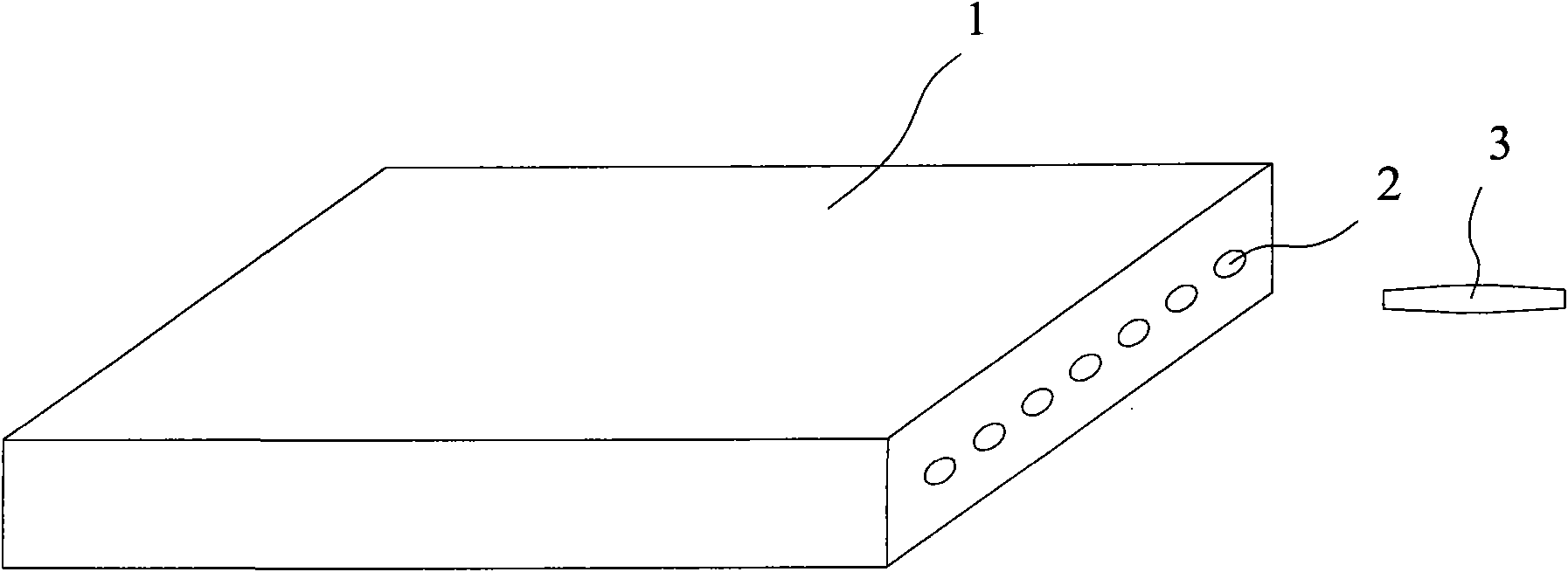
[0026] Such as figure 1 As shown, the splicing structure of the present invention includes: blind holes 2 arranged on the side of the floor body 1 and distributed along the length direction of the side, and wooden tenon strips 3 that can be inserted into and snapped into the blind holes 2 . Both ends of the tenon strip 3 have tapered sections of appropriate length, which facilitates the insertion of the tenon strip 3 into the blind hole 2 and can be firmly snapped into the blind hole 2 after insertion. The blind hole 2 can be a square hole or a round hole, and the cross section of the dowel bar 3 can be a square or a circle that matches the shape of the cross section of the blind hole 2 .

[0027] Because the present invention adopts the structure in which the tenon strip 3 is inserted into the blind hole 2, the processing of the blind hole 2 is faster and more convenient than the processing of the slot, and the processing of the tenon strip 3 can also be processed separately ...


PUM


Abstract

The invention provides a floor block connecting structure, which comprises a blind hole arranged at the side edge of the floor block, and a wood plug strip which can be plugged into and clamped to be fixed in the blind hole. The invention also provides a floor block, which comprises a floor body, wherein the side surface of the floor body is provided with more than one blind hole distributed along the length direction of the side surface, the floor bodies are spliced together via the wood plug strip which can be plugged into and clamped to be fixed in the blind hole. The invention uses the wood plug strip and the blind hole to splice the floor blocks, the blind hole can be processed by a punching machine very conveniently, the wood plug strip can be independently manufactured in batches, the prior complicated process of milling tongue-shaped objects matched with a clamping groove is omitted, and the production efficiency is greatly increased.

Description

technical field [0001] The invention relates to a connection structure of floor boards and a floor board adopting the structure. Background technique [0002] Existing floors are usually joined in two ways: [0003] The first connection method is to fix the supporting floor on the ground in advance (commonly known as the wool floor), and then glue the floor to the wool floor, or use steam nails to nail the floor to the wool floor. The connection method of this floor is more complicated, and it is more difficult to replace the floor. [0004] The second connection method is to lay the floor flat on the ground, and the floor boards are fixed by a connection part formed by a tongue on the side of the floor board and a card slot on the side of the floor board matching the floor boards between the floor boards. Although this connection method is convenient for installation, it increases the cost and wastes timber resources due to the need for regrooving and tenon milling of the...

Claims


Application Information

Patent Timeline
Patent Type & Authority Applications(China)
IPC IPC(8): E04F15/02
Inventor 张士元张方文李银凤
Owner BEI JING NEW BUILDING MATERIALGRP
Why Eureka
Try Eureka